This small post shows how to control speed and direction of rotation of bipolar stepper motor using Arduino UNO board and L293D motor driver chip.
The stepper motor used in this example is just a PC CD-ROM (or DVD-ROM) drive which has 4 wires.
Proteus simulation of the example is provided at the end of the topic.
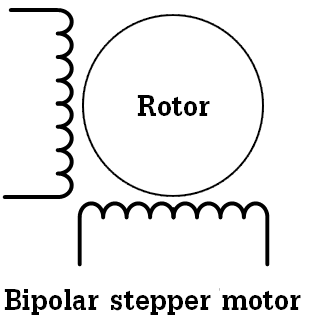
Basically there are two types of stepper motors: bipolar and unipolar. The bipolar stepper motor is a two-phase brushless motor which has two coils (windings), this motor has 4 wires (2 wires for each coil).
The other type is the unipolar stepper motor, it is 4-phase brushless motor which has 5 or 6 wires.
The popular controlling modes of of the stepper motor are: full step and half step. The full step can be divided into 2 types: one-phase and two-phase.
In full step one-phase mode the driver energizes one coil at a time. This type of controlling requires the least amount of power but provides the least torque.
In full step two-phase mode the driver energizes the two coils at the same time. This mode provides the highest torque but it requires twice as much power as one-phase mode.
Half step mode is a combination of the two full step modes (one-phase and two-phase). This mode increases accuracy by dividing each step by 2. it requires power in-between one-phase and two-phase modes, torque also is in-between.
There is another controlling type called microstepping, this type is more accurate than the half step mode, it requires two sinusoidal current sources with 90° shift.
In this example I’m going to use the full step two-phase mode for controlling the bipolar stepper motor.
The following image shows a simple schematic of the bipolar stepper motor:
To be able to control the bipolar stepper motor, two H-bridge circuits are required. In this example I’m going to use L293D quadruple half-H driver which can work as dual H-bridge driver. This chip is small, low cost and easy to use, these make it a good choice for students and hobbyists, in this blog, I used it in some DC motor control projects.
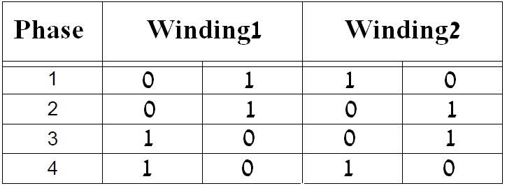
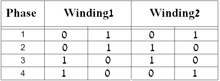
In the full step control mode always both windings are energized at the same time according to the following two tables where first table shows the driving sequence for one rotation direction and second table for the other direction:
Related Projects:
Arduino Unipolar Stepper Motor Control
Hardware Required:
- Arduino UNO board
- Bipolar stepper motor
- L293D motor driver chip —-> datasheet
- 10k ohm potentiometer
- Pushbutton
- Power source with voltage equal to motor nominal voltage
- Bread board
- Jumper wires
Arduino bipolar stepper motor control circuit:
Example circuit diagram is shown below.
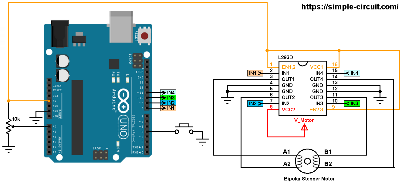
All grounded terminals are connected together.
The L293D chip has 16 pins with 4 inputs (IN1, IN2, IN3 and IN4) and 4 outputs (OUT1, OUT2, OUT3 and OUT4). The 4 outputs are connected to the bipolar stepper motor as shown in the circuit diagram.
The 4 inputs are connected as follows:
IN1 to Arduino pin 8
IN2 to Arduino pin 9
IN3 to Arduino pin 10
IN4 to Arduino pin 11
The L293D has 2 VCC pins: VCC1 (pin #16) and VCC2 (pin #8). VCC1 is connected to Arduino +5V pin. VCC2 is connected to another power source (positive terminal) with voltage equal to motor nominal voltage, it’s labeled in the circuit diagram as V_Motor (V_Motor = motor voltage). So if we have a stepper motor with nominal voltage of 5V we’ve to connect VCC2 to +5V (Arduino 5V output shouldn’t be used) and if the stepper motor nominal voltage is 12V we’ve to connect VCC2 to +12V (negative terminal of this source is connected to circuit ground)…
The 10k ohm potentiometer is used to control the speed of the stepper motor, its output pin is connected to Arduino analog pin 0.
The push button which is connected to Arduino pin 4 is used to change the rotation direction of the stepper motor.
Arduino bipolar stepper motor control code:
In this example I used Arduino stepper motor library (built-in) which simplifies the code, it is included in the code using the following line:
1 | #include <Stepper.h> |
The stepper motor which I used in this project has 20 steps per one revolution, it is defined in the code as shown below:
1 | #define STEPS 20 |
and the connection of the control lines of the stepper motor are defined as:
1 | Stepper stepper(STEPS, 8, 9, 10, 11); |
Using the function stepper.step(direction_) the stepper motor moves according to the variable direction_, in this example this variable may be 1 or -1. If direction_ = 1 the motor will move in the first direction and if direction_ = -1 the motor will move in the other direction.
When ever the pushbutton is pressed, the variable direction_ will be inverted (1 or -1).
Rest of code is described through comments.
1 2 3 4 5 6 7 8 9 10 11 12 13 14 15 16 17 18 19 20 21 22 23 24 25 26 27 28 29 30 31 32 33 34 35 36 37 38 39 40 41 42 43 44 45 46 47 48 49 50 51 52 53 54 55 56 57 58 59 60 61 62 63 64 65 66 67 | /* * Bipolar stepper motor speed and direction control with Arduino. * Full step control. * This is a free software with NO WARRANTY. * http://simple-circuit.com/ */ // include Arduino stepper motor library #include <Stepper.h> // change this to the number of steps on your motor #define STEPS 20 // create an instance of the stepper class, specifying // the number of steps of the motor and the pins it's // attached to Stepper stepper(STEPS, 8, 9, 10, 11); const int button = 4; // direction control button is connected to Arduino pin 4 const int pot = A0; // speed control potentiometer is connected to analog pin 0 void setup() { // configure button pin as input with internal pull up enabled pinMode(button, INPUT_PULLUP); } int direction_ = 1, speed_ = 0; void loop() { if ( digitalRead(button) == 0 ) // if button is pressed if ( debounce() ) // debounce button signal { direction_ *= -1; // reverse direction variable while ( debounce() ) ; // wait for button release } // read analog value from the potentiometer int val = analogRead(pot); // map digital value from [0, 1023] to [5, 100] // ===> min speed = 5 and max speed = 100 rpm if ( speed_ != map(val, 0, 1023, 5, 100) ) { // if the speed was changed speed_ = map(val, 0, 1023, 5, 100); // set the speed of the motor stepper.setSpeed(speed_); } // move the stepper motor stepper.step(direction_); } // a small function for button debounce bool debounce() { byte count = 0; for(byte i = 0; i < 5; i++) { if (digitalRead(button) == 0) count++; delay(10); } if(count > 2) return 1; else return 0; } |
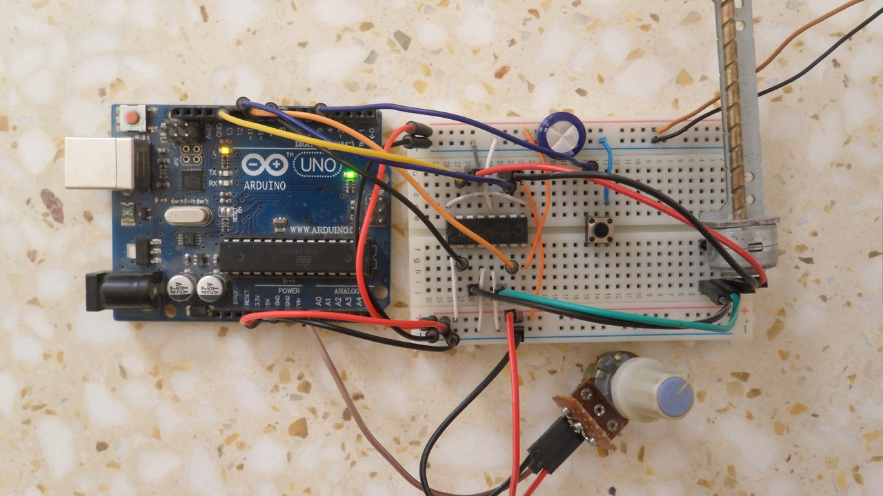
The following video shows a simple hardware circuit of the project:
and this video shows Proteus simulation
Arduino + stepper motor Proteus simulation:
Simulation file download link is below.
Arduino + Bipolar stepper motor


Hi,
I was desperately searching the web for a sketch and circuit to drive a bipolar stepper motor. I found a lot of proposals to drive motors with 5 wires and ULN2003 chips but nothing for 4 wire motors. Since I had a L293 in my stock of components, I started looking for bipolar and L293 and found “simple projects”. I set everything up on a breadboard using an Arduino Pro Mini. Right after applying the power, the motor started to turn.
Thank you very much for your kind effort.
Christoph from Germany
Hi!
I can’t get the motor to turn… using a Nema 17 42 series.
Can you help me out?
https://gabrielortiz.net/videos/20210302_121457.mp4
Hey, could you make the motor turn finally?
Hey. Thanks for this!
1. Is there a way I could replace the direction button with Number of steps the stepper motor moves before reversing its direction?
2. Plus how can I remove the loop?
I am stuck on this in my FYP with a deadline reaching soon. Haven’t used or learned Proteus in my entire degree. Your help will be appreciated
where do you get the arduino’s library for proteus?
i’m using different library, but can’t running like simulation in your videos.
could you help me, please!
not working
ISIS Release 8.09.00 (Build 27865) (C) Labcenter Electronics 1990- 2019.
Compiling design ‘C:\Users\DELL\Desktop\Arduino + Bipolar stepper motor.pdsprj’.
Netlist compilation completed OK.
Netlist linking completed OK.
Partition analysis completed OK.
Simulating partition 1
PROSPICE 8.08.00 (Build 27367) (C) Labcenter Electronics 1993-2019.
mixed model AVR2.DLL failed to authorize – Missing or invalid Customer Key.. [AU1]
Loaded netlist ‘C:\Users\DELL\AppData\Local\Temp\LISA9501.SDF’ for design ‘Arduino + Bipolar stepper motor.pdsprj’
Real Time Simulation failed to start.
Simulation FAILED due to fatal simulator errors.
this much error is coming
Try with newer version of Proteus ISIS (for example version 8.6 or higher)!
Hi, could you send me the file of protues simulation for Arduino + Bipolar stepper motor please? i cant download it.
Download link is working well!
Unzip it to get Proteus simulation file.
https://drive.google.com/open?id=1awcsyLfZkcnqw9PVLplKRvV71Rjt947O