DIY ESC with Arduino UNO
This topic shows how to build a sensorless brushless DC (BLDC) motor controller or simply an ESC (Electronic Speed Controller) with an Arduino UNO board.
There are two types of brushless DC motors: sensored and sensorless. Sensored BLDC motor has built-in 3 hall effect sensors, these sensors detect the rotor position of the BLDC motor. Controlling a sensored BLDC motor is easy since we know the rotor position like what was done in the project below:
Sensored brushless DC motor control with Arduino
The commutation of the sensored BLDC motor is done according to the hall effect sensors state.
Sensorless BLDC motor doesn’t have any sensor to detect its rotor position, its commutation is based on the BEMF (Back Electromotive Force) produced in the stator windings.
The main advantage of sensorless BLDC motor control is lower system cost and the main disadvantage is the motor must be moving at minimum rate to produce sufficient BEMF to be sensed.
How it works:
When the BLDC motor rotates, each winding (3 windings) generates BEMF opposes the main voltage. The 3 generated BEMF signals are 120° out of phase which is the same as the hall effect sensor signals. The figure below shows the relationship between the hall effect signals and the BEMF signals:
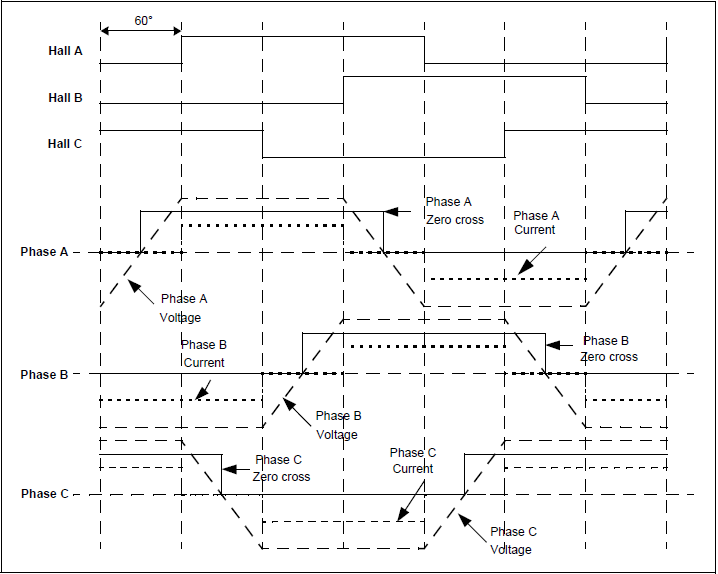
As shown in the figure above, the BEMF signals are not synchronized with the hall effect sensor signals (phase shift of 30°). In every energizing sequence, two windings are energized (one connected to positive and the other to negative) and the third winding is left open (floating). The floating winding is used to detect the zero crossing, thus, the combination of all 3 zero cross over point are used to generate the energizing sequence. Totally we’ve 6 events:
Phase A zero crossing: from high to low and from low to high
Phase B zero crossing: from high to low and from low to high
Phase C zero crossing: from high to low and from low to high
How to detect the zero crossing event:
The easiest way to detect the zero crossing events is by using comparators. The comparator has 3 main terminals: 2 inputs (positive and negative) and an output. Comparator output is logic high if the positive voltage is greater than the negative voltage, and logic low if the positive voltage is lower than the negative voltage.
Basically 3 comparators are needed for this project, connections are done as shown in the figure below (example for phase B). Each phase requires a similar circuit.
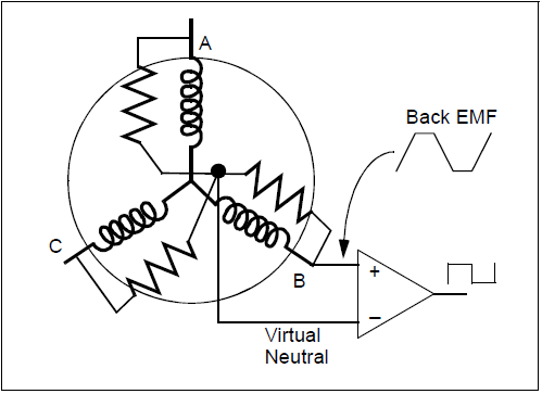
The virtual natural point is the same for all the 3 comparators, it is generated using 3 resistors. When the BEMF generated in the floating (open) winding crosses the zero point towards positive side, the comparator output makes a transition from low-to-high. When the BEMF generated in the floating winding crosses the zero point towards negative side, the comparator output makes a transition from high-to-low. By having three such comparator circuits, one on each of the phases gives three digital signals corresponding to the BEMF signal in the windings. The combination of these three signals is used to derive the commutation sequence.
Hardware Required:
- Arduino UNO or similar board (Nano, Mini…) —> ATmega328P datasheet
- Brushless DC (BLDC) motor
- 6 x 06N03LA N-type mosfet (or equivalent) – datasheet
- 3 x IR2104S (IR2104) gate driver IC – datasheet
- 6 x 33k ohm resistor
- 3 x 10k ohm resistor
- 6 x 100 ohm resistor
- 3 x IN4148 diode
- 3 x 10uF capacitor
- 3 x 2.2uF capacitor
- 2 x pushbutton
- 12V source
- Breadboard
- Jumper wires
Sensorless BLDC motor control with Arduino circuit:
Project circuit schematic is shown below.
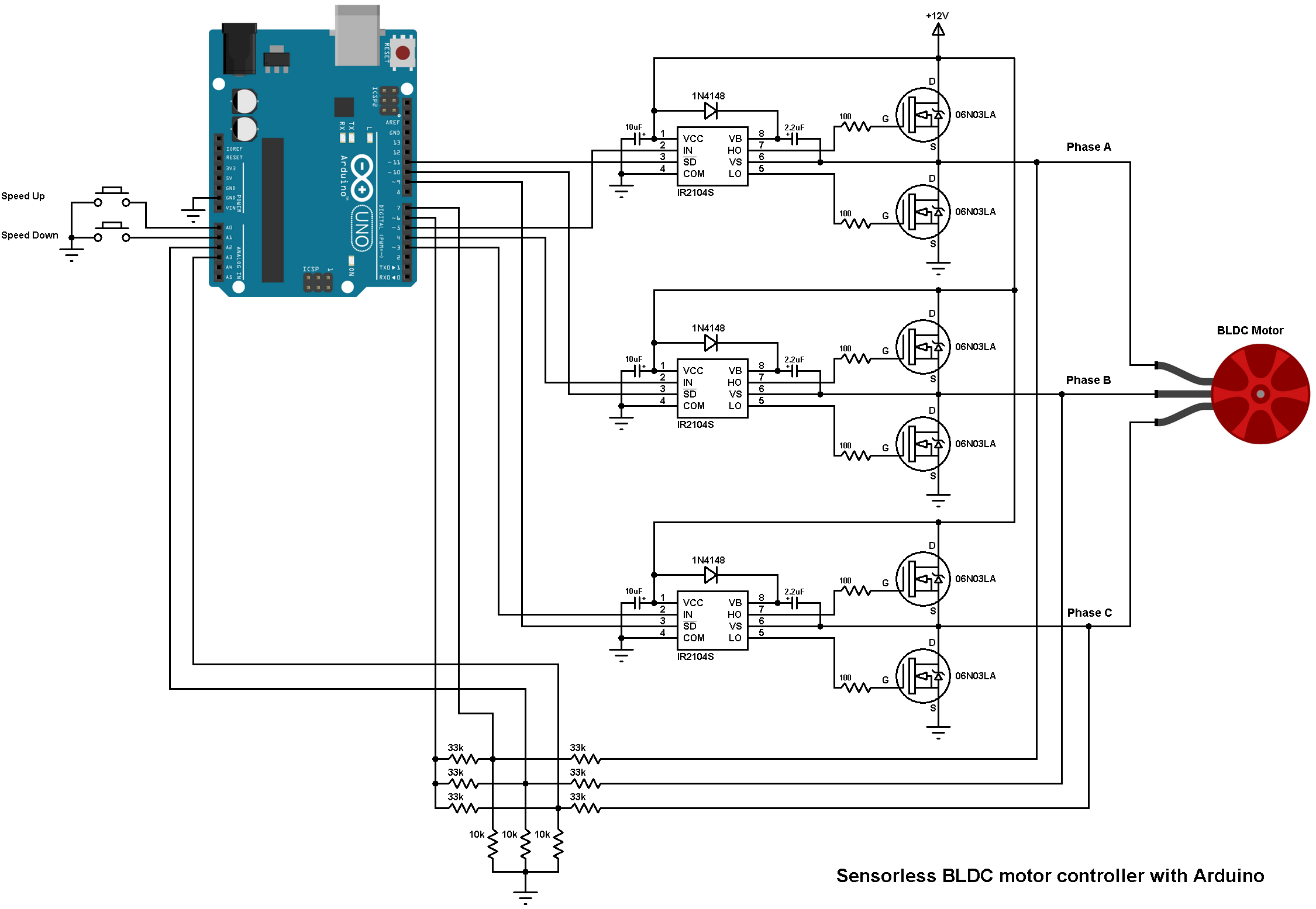
Note that all grounded terminals are connected together.
In the circuit there are 2 pushbuttons, one is used to increase BLDC motor speed and the 2nd one is used to decrease it.
The first three 33k (connected to motor phases) and the three 10k resistors are used as voltage dividers, because we can not supply the microcontroller with 12V, the other three 33k resistors generate the virtual natural point. The virtual natural point is connected to Arduino pin 6.
The Arduino UNO board is based on the ATmega328P microcontroller which has one analog comparator. The positive input of this comparator is on Arduino uno pin 6 (AIN0) and the negative input can be pin 7 (AIN1), A0 (ADC0), A1 (ADC1), A2 (ADC2), A3 (ADC3), A4 (ADC4) or A5 (ADC5). So I connected the virtual natural point to the positive pin of the analog comparator (pin 6), phase A BEMF to pin 7 (AIN1), phase B BEMF to pin A2 and phase C BEMF to pin A3. Each time the comparator compares the virtual point with the BEMF of one phase (this is done in the software). This minimizes the hardware needed and simplifies the circuit.
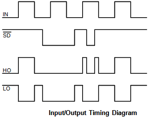
The IR2104S chips are used to control high side and low side mosfets of each phase. The switching between the high side and the low side is done according to the control lines IN and SD. The figure below shows input and output timing diagram:
The SD lines of the three IR2104S are connected to pins 11, 10 and 9 respectively for phase A, phase B and phase C. The Arduino UNO can generate PWM signals on that pins where only high side mosfets are PWMed.
Sensorless BLDC motor control with Arduino code:
The code below does not use any BLDC motor library.
As mentioned above, Arduino pins 9, 10 and 11 can generate PWM signals where pin 9 and pin 10 are related with Timer1 module (OC1A and OC1B) and pin 11 is related with Timer2 module (OC2A). Both Timer modules are configured to generate a PWM signal with a frequency of about 31KHz and a resolution of 8 bits. The duty cycles of the PWM signals are updated when a pushbutton is pressed (speed up or speed down) by writing to their registers (OCR1A, OCR1B and OCR2A).
The analog comparator compares the positive input AIN0 (Arduino pin 6) with the negative input which can be AIN1 (pin 7), ADC2 (pin A2) or ADC3 (pin A3). When the positive pin voltage is higher than the negative pin voltage, the output of the analog comparator ACO is set, and when the positive pin voltage is lower than the negative pin voltage, ACO is cleared.
In this project I used the analog comparator interrupt and I used its interrupt on rising (transition from low to high) and interrupt on falling (transition from high to low), this makes the zero crossing events interrupt the microcontroller.
To fully understand the code, please read the ATmega328 datasheet!
1 2 3 4 5 6 7 8 9 10 11 12 13 14 15 16 17 18 19 20 21 22 23 24 25 26 27 28 29 30 31 32 33 34 35 36 37 38 39 40 41 42 43 44 45 46 47 48 49 50 51 52 53 54 55 56 57 58 59 60 61 62 63 64 65 66 67 68 69 70 71 72 73 74 75 76 77 78 79 80 81 82 83 84 85 86 87 88 89 90 91 92 93 94 95 96 97 98 99 100 101 102 103 104 105 106 107 108 109 110 111 112 113 114 115 116 117 118 119 120 121 122 123 124 125 126 127 128 129 130 131 132 133 134 135 136 137 138 139 140 141 142 143 144 145 146 147 148 149 150 151 152 153 154 155 156 157 158 159 160 161 162 163 164 165 166 167 168 169 170 171 172 173 174 175 176 177 178 179 180 181 182 183 184 185 | /* Sensorless brushless DC (BLDC) motor control with Arduino UNO (Arduino DIY ESC). * This is a free software with NO WARRANTY. * https://simple-circuit.com/ */ #define SPEED_UP A0 #define SPEED_DOWN A1 #define PWM_MAX_DUTY 255 #define PWM_MIN_DUTY 50 #define PWM_START_DUTY 100 byte bldc_step = 0, motor_speed; unsigned int i; void setup() { DDRD |= 0x38; // Configure pins 3, 4 and 5 as outputs PORTD = 0x00; DDRB |= 0x0E; // Configure pins 9, 10 and 11 as outputs PORTB = 0x31; // Timer1 module setting: set clock source to clkI/O / 1 (no prescaling) TCCR1A = 0; TCCR1B = 0x01; // Timer2 module setting: set clock source to clkI/O / 1 (no prescaling) TCCR2A = 0; TCCR2B = 0x01; // Analog comparator setting ACSR = 0x10; // Disable and clear (flag bit) analog comparator interrupt pinMode(SPEED_UP, INPUT_PULLUP); pinMode(SPEED_DOWN, INPUT_PULLUP); } // Analog comparator ISR ISR (ANALOG_COMP_vect) { // BEMF debounce for(i = 0; i < 10; i++) { if(bldc_step & 1){ if(!(ACSR & 0x20)) i -= 1; } else { if((ACSR & 0x20)) i -= 1; } } bldc_move(); bldc_step++; bldc_step %= 6; } void bldc_move(){ // BLDC motor commutation function switch(bldc_step){ case 0: AH_BL(); BEMF_C_RISING(); break; case 1: AH_CL(); BEMF_B_FALLING(); break; case 2: BH_CL(); BEMF_A_RISING(); break; case 3: BH_AL(); BEMF_C_FALLING(); break; case 4: CH_AL(); BEMF_B_RISING(); break; case 5: CH_BL(); BEMF_A_FALLING(); break; } } void loop() { SET_PWM_DUTY(PWM_START_DUTY); // Setup starting PWM with duty cycle = PWM_START_DUTY i = 5000; // Motor start while(i > 100) { delayMicroseconds(i); bldc_move(); bldc_step++; bldc_step %= 6; i = i - 20; } motor_speed = PWM_START_DUTY; ACSR |= 0x08; // Enable analog comparator interrupt while(1) { while(!(digitalRead(SPEED_UP)) && motor_speed < PWM_MAX_DUTY){ motor_speed++; SET_PWM_DUTY(motor_speed); delay(100); } while(!(digitalRead(SPEED_DOWN)) && motor_speed > PWM_MIN_DUTY){ motor_speed--; SET_PWM_DUTY(motor_speed); delay(100); } } } void BEMF_A_RISING(){ ADCSRB = (0 << ACME); // Select AIN1 as comparator negative input ACSR |= 0x03; // Set interrupt on rising edge } void BEMF_A_FALLING(){ ADCSRB = (0 << ACME); // Select AIN1 as comparator negative input ACSR &= ~0x01; // Set interrupt on falling edge } void BEMF_B_RISING(){ ADCSRA = (0 << ADEN); // Disable the ADC module ADCSRB = (1 << ACME); ADMUX = 2; // Select analog channel 2 as comparator negative input ACSR |= 0x03; } void BEMF_B_FALLING(){ ADCSRA = (0 << ADEN); // Disable the ADC module ADCSRB = (1 << ACME); ADMUX = 2; // Select analog channel 2 as comparator negative input ACSR &= ~0x01; } void BEMF_C_RISING(){ ADCSRA = (0 << ADEN); // Disable the ADC module ADCSRB = (1 << ACME); ADMUX = 3; // Select analog channel 3 as comparator negative input ACSR |= 0x03; } void BEMF_C_FALLING(){ ADCSRA = (0 << ADEN); // Disable the ADC module ADCSRB = (1 << ACME); ADMUX = 3; // Select analog channel 3 as comparator negative input ACSR &= ~0x01; } void AH_BL(){ PORTB = 0x04; PORTD &= ~0x18; PORTD |= 0x20; TCCR1A = 0; // Turn pin 11 (OC2A) PWM ON (pin 9 & pin 10 OFF) TCCR2A = 0x81; // } void AH_CL(){ PORTB = 0x02; PORTD &= ~0x18; PORTD |= 0x20; TCCR1A = 0; // Turn pin 11 (OC2A) PWM ON (pin 9 & pin 10 OFF) TCCR2A = 0x81; // } void BH_CL(){ PORTB = 0x02; PORTD &= ~0x28; PORTD |= 0x10; TCCR2A = 0; // Turn pin 10 (OC1B) PWM ON (pin 9 & pin 11 OFF) TCCR1A = 0x21; // } void BH_AL(){ PORTB = 0x08; PORTD &= ~0x28; PORTD |= 0x10; TCCR2A = 0; // Turn pin 10 (OC1B) PWM ON (pin 9 & pin 11 OFF) TCCR1A = 0x21; // } void CH_AL(){ PORTB = 0x08; PORTD &= ~0x30; PORTD |= 0x08; TCCR2A = 0; // Turn pin 9 (OC1A) PWM ON (pin 10 & pin 11 OFF) TCCR1A = 0x81; // } void CH_BL(){ PORTB = 0x04; PORTD &= ~0x30; PORTD |= 0x08; TCCR2A = 0; // Turn pin 9 (OC1A) PWM ON (pin 10 & pin 11 OFF) TCCR1A = 0x81; // } void SET_PWM_DUTY(byte duty){ if(duty < PWM_MIN_DUTY) duty = PWM_MIN_DUTY; if(duty > PWM_MAX_DUTY) duty = PWM_MAX_DUTY; OCR1A = duty; // Set pin 9 PWM duty cycle OCR1B = duty; // Set pin 10 PWM duty cycle OCR2A = duty; // Set pin 11 PWM duty cycle } |
Sensorless BLDC motor control with Arduino video:
The video below shows how project is working.
References:
Microchip AN970 document
https://www.microchip.com/


Hello, the project is not working on Proteus, can you help??
Hello, the project is not working on Proteus, can you help?
How to modify this driver to drive a 220v bldc motor ??
This is a good project for electrical engineering students to test their electrical and control knowledge.
i see some escs using S8050 instead of IR2104. What do you think? thanks!
I want to control with your circuit a 1kW AC motor. Is it possible?
Hey, Simple Projects.
I tweked the ISR function. Before “for” loop i’ve copied current motor speed to the buffer. Then whenever “i” in FOR loop is decremented, I rise PWM DUTY by 2 and immiedently set it.
This simple change REALLY made this ESC useful -> now no matter what load is applied motor is in sync with electric commutator, efficiency went WAY up!
With some tweking to the ISR, low side current measurement, this project can be super proffesional. I’ve made few prototypes that can handle 25A current. My Redox 500/14000 works like absolute beast under any load!
Hi Maciek G! Exactly how did you do it? Can you explain better the logic? Can you post your variation of the code, or send me this part fo the code? If you raise the PWM by two on the debounce section, that get’s the “i” from 10 to 0 (so 10 times PWM raised by a factor of two in a single interrrupt) the speed will increase to pwm 255 in a matter of 10 interrupts! It will speed to max no matter if the motor has load or not! How did you do it exacly? Do you mind to share? Thanks! I can send my email if needed!
i made the circuit with exact components and when i power on the circuit motor start vibrating. When we apply external rotational force(with hand), it starts working fine. but It should not need that external starter force. So what should I change to make it work. Your response will be appreciated. i need to get it done for my project.
I tried the exact circuit I used the mosfets you suggested as well as the drivers and it worked well many thanks
Hi I want to rotate my motor of above setup in reverse direction . what should I do ? kindly anyone guide me ..
Can anyone please give me advise . I want to do the project to run a 3 phase bldc motor with 100V dc or 300V dc power. Im using the same schematics as the 12V dc motor controler circuit with arduino using Ir2104 and mosfet Ir840. Do I have to change the values of the two capacitors and to which value? And to what value do I have to change the resistors? And would it be a good idea to use one power source to power the mosfets and the ir2104 and Arduino by using voltage deviders?
I have a 36 pole samsung motor and would like to do the project to run it with 100V dc or 300V dc. Im using the same schematics as for the 12V dc motor. Can anyone tell me to what values I have to change the resisters and if I have to change the values of the two capacitors also and to what value?
how can ı use potentiometer in this project please help
Hello, will the same set up is going to work when I am going to use an out runner bldc motor used in e-bikes?
I have required of block diagram of sensorless bldc motor control with arduino uno. so, plz request you to send it quickly
Hello. Me and my friends have tried to adapt this project into one where we can supply the motor with up to 150V while reducing the voltage incoming to Arduino to protect it from destruction. It worked, but somehow strange – the motor only starts rotating when the PwM duty cycle is set to maximum (255) and the motor actually turns off immediately after we try to reduce it. We can’t find any fault in the schematics or in the script. Do you please have any advice on what might be causing that and how to fix it? Thank you in advance for reply!
Hi I done the circuit with mosfet ipp055n03 and gate driver ir2104 and connect to bldc motor and arduino code as same as you but my bldc motor cannot rotate and make noise. But at some time, I try push the motor shaft, the motor rotates for a few seconds and then stop rotate and make noise again. Is there anyone has solution for this?
I kinda have the same problem.. When i press reset on Arduino the motor rotates foe a few seconds and then it gets stuck and makes screeching noise.
Can anyone please help me with this problem ?
Hi,
Great tutorial! I build this on a PCB and all is working well 🙂
One question about the commutation sequence functions (i.e AH_BL):
void AH_BL(){
PORTB = (1<<PHB_EN);
PORTD &= ~((1<<PHB_IN) | (1<<PHC_IN));
PORTD |= (1<<PHA_IN);
TCCR1A = 0; // Turn pin 11 (OC2A) PWM ON (pin 9 & pin 10 OFF)
TCCR2A = 0x81; // Clear on compare match and PWM_PHASE_CORRECT
}
For this step, we set PHB Low Side to be ON since it's /SD pin is being driven HIGH and are allowing PHA High Side IN pin to be PWM'd ON and OFF but the /SD pin for PHA is never asserted?
How does the IR2104 IC pass through the PWM input signal without the /SD pin being asserted?
After some careful review, think I figured it out:
* PHB /SD is set to be logic HIGH
* PHA IN is also set to be logic HIGH
* PHA /SD is PWM’d ON/OFF.
* When ON: So IR2104 IC passes sets HO: HIGH and LO: LOW
* When OFF: HO: LOW and LO: LOW
Mistook the PWM to be connected to the IN pin, when in actuality it’s connected to /SD
Hai @Brian.. are you really done this project using ardiuno… are u made any change in circuit as well as in program code.. please help me i want to complete this as my project .. you can touch with me via mail [email protected].. this is my MAIL ID ..i tried but didn’t get proper output .. meanwhile the moter produce noice.. please make some favour.. im waiting for your kind reply..
Hi! I have patched the circuit. I’m using irFz44n. When I run the circuit, Motor vibrates and then stops. My motor is 2212/10T. Is there any problem with the code? I connected phase A with Black, B with Yellow C with red. Please Help
the same problem Plz help me
Hi, I really can’t understand the debounce code into the interrupt routine, can anyone explain it to me?
void INT_EXT_ISR(void){
// BEMF debounce
for(int8 j = 0; j < 20; j++) {
if(bldc_step & 1) {
if(input(PIN_B0)) j -= 1;
}
else {
if(!input(PIN_B0)) j -= 1;
}
}
bldc_move();
SET_PWM_DUTY();
}
Thanks in advance
I think it works something like this (going off the original code – not what’s copied and pasted in your post above):
1) The Analog Compare Interrupt Fires
2) Based on BLDC_STEP, check that the Analog Compare Output is at the expected logic level (HIGH for odd step, LOW for even step)
3) “Debounce” glitches by making sure we get 20 consecutive correct readings
4) If any of the readings are incorrect, decrement the counter so the last measurement (with the wrong logic level) doesn’t count
5) Eventually exit the for loop and increment to the next step of the commutation sequence
I use 6 output 600v ir2130 driver with ir840 and irfp450 .I use also opto isolated HPCPL2531. THE 12V 1KV MOTOR work very good.I replace the B-EMF resistor with tow 270k and 4,7k.for each of the 3 comparators so.i have 2.5v for the half of 320vdc.I try to connect a bldc air conditionihg compressor and all make boom. Have you any idea how to continue?
Hi can you provide the flowchart for the arduino code?
Hi i used ipp055n03 istead 06n03la and used 23a 12v alkaline battery as the source but it does not work. Can anyone tell me the problems?
The code is for a specific integrate drive,
Sorry for this question… Really this circuit will work.. please reply… If there is any modifications should do in circuit means.. please let me know..
I tried this circuit , the motor getting vibrate.. I dosent rotate..
Hai simple circuit… Why we need to connect driver ic’s 6 th pin with MOSFETs D & S connection
My next question is the circuit which you used in speed control bldc in youtube is same or not the circuit which you posted in web blog
Sir please explain me , why we need to connect drive’s 6 pin with MOSFETs Source drain supply
An N-type MOSFET to be ON you’ve to apply a sufficient voltage between its gate (G) and source (S) pins, and that’s what the IR2104 does. Each time the IR2104 applies this voltage using pins 7 & 6 for the upper mosfet and pin 5 (& of course the GND or com pin) for the lower mosfet.
Hi simple circuit, can you give me the proteus file for this project? thanks
Sorry, I’ve no Proteus simulation file for this project.
Hello nice work on the above but I was wondering if I was using 36 v and was power a bigger motor would this still work I am going to use better mosfets because I am expecting more current but my main concern was the gate driver will it work with 36v?
plz how to tell me the biggest capacitor values?
You may use 25V 2200 uF.
Noel Nop we tayed it.
The algorithm mast be changed for Mosfet drive. And if you manage to get it to work, then its Only works on low speed.
Mr james.the 2 botton control is speed control. No stop or direction control.
To Direction managing U need a min 2, optimal 3 Hall sensors and a table to detect rotation, and adapte algrotihm Wave generation. Or separat Back EMf commperator.. ..
is it possible to use that device to higher voltage bldc motor? example to 320v dv motor? the we can find in a washing machine.
hi! good day! can i use that device to my disc type direct drive washing machine motor? please help.
is that devise is available in the market? where can i buy a ready device that you are using. please help
Thank You
How do I turn the clockwise with one button and with another button change the rotation counterclockwise?
If i’m only using the two buttons to control the speed, is there any advantage of using the lm339 over the internal comparators? And should I tie the rest of the analog in pins to gnd for noise immunity? cheers
Hey i tried this circuit with the IR2101 and 2104, the code and everything works well. I’m able to run an old alternator as bldc even. Now i want to scale it up a bit and use TO-220’s. could you recommend some fets for a 24v system? i was looking for mosfets with the same gate charge, but still need a recommendation, cheers from AUS
i run this code with few modifications on a Samsung BLDC drum like gerard morin did in his videos. as i did more research on the circuit i noticed that the duty-cycle went down automaticaly to the min-duty-cycle that i set in the code. the motor starts automaticaly with a duty-cycle of 240 when the voltage is set to 90V or more. then when i increase the voltage to 200V the drum automatically ‘corrects’ its given duty-cycle and decreases it. can you give me a hint why this is happening? i did this testing only on the big BLDC drum and have not tried another motor. https://youtu.be/QBSD1JfCnUA if you read this and like to comment i would be very happy 🙂 thx and big regards from austria.
The duty cycle is set by the Arduino microcontroller and it’s not related to motor supply voltage.
Since the resolution of the PWM signal is 8-bit, the duty cycle may vary between 0 and 255. If duty cycle is zero the motor will stop. Using a min duty cycle prevents the motor from stopping, you can test which minimum duty is adequate for your application.
Also, the duty cycle is controlled from the 2 push buttons, after your motor starts try decreasing the duty cycle!
it behaves exactly as you mentioned and can be clearly seen in the serial monitor if we do the necessary addition to the code. what we are also trying is to integrate the PWM library so that we can use more frequencies to play with. but it seems to be difficult from my point of view.
There is no need for the PWM library! you can change the frequency with Timer1 and Timer2 registers (TCCR1A, TCCR1B, TCCR2A and TCCR2B), ATmega328P datasheet shows how to do that.
yes but there only a few options. i would like to run the drum with for example 120kHz. if i use 0x01 for TCCR1A the frequenzy is preset to 31kHz. don’t understand how to achieve this.
hello. I have build my circuit for the same Samsung BLDC drum.
It did not worked.
can U send me your modifications?
[email protected].
I don’t get any signal after the 2104 and the mosfet is opened all the time.
I think because of the virtual point the resistors need to be changed.
Hello renemeschuh. I have build my circuit for the same Samsung BLDC drum.
It did not worked.
can U send me your modifications?
[email protected].
I don’t get any signal after the 2104 and the mosfet is opened all the time.
I think because of the virtual point the resistors need to be changed.
Very nice guide. From what I see, only one PWM should be required, since all three PWM Generators are outputing the same frequency and same duty cycle, so only one PWM pin could simplify both hardware and software.(Correct me when I am wrong)
It would be interesting to see the specific operation to not only control the speed, but also control it’s direction. Good project anyways!
I’m whaiting for my 4CH oscilloscope & function/Arb. waveform generator. I mad successful contakt with Nico. Till the Oscilloscope not arrives, i can’t chek the malfunction of my cirkuit.
Alex please send me a email. And gone send you the Hall sensor pin layout.
ok
[email protected]
what the mosfet use? except 06N03LA. what similiar mosfet 06N03LA?
wunschfee thanks for sharing
but the link is no longer available
can give more details if it worked in some way with 100 volts, and show the video
see you soon
Here my email address to wunschfee[at]freemail.hu.
For me the mentioned ciruit above did not worked. With the IRF840 mofet. I also tried a faster, IRF530 100v mosfet.
I used a 0.8A 90volt power suply. For testing my gol is a 650v/1100v motor driver. Becouse on higher voltage takes les amper.
Gerald Moris usesa external Motor river cirkuit witch Hi has opend, and its a Frequency generator Motor drive, not a PWM drive. The. The built in 4 cabel twinn Tacho signal generator is working fine in my setup. https://ibb.co/FxxJCv9
I cust recived a NAND chips to trie out.
i just send you an email wuns 😉 check it 😉
Hi Nico
You mention that you have already assembled the project and that you only wait for the IRF840.
I consider that the program that presents here simple projects, is already practical.
1.- Start the project as it is presented here, with the voltages output that proposes 12 volts that are applied to the mosfet. in your case they would be the mosfet IRF840
2.-Test it with a bruless guy engine as the video shows it. And if everything works, it’s fine.
3.- Increase the voltage to where you propose Simple projects.
4.-change the engine and put the 36 coils and feed the output of the mosfet to about 48 to 60 volts.
5. If the motor moves and it is working, raise the voltage to about 80-100 volts.
6.- Depending on the results, and if they are good, increase the output voltage of the mosfet to about 169 cd. (rectify the 120 AC, you get the 169 CD.) If you can check the revolutions in each voltage increase
7.- And see the results, if they are favorable, if you want to increase the voltage
What I am saying is that if the Simple Projects project is already functional, it has to be coupled to the 36 poles motor.
The project of Thomas and Gerard of the pdf, as we commented already it was corrected the system of protection and the divider of voltage.
performing the steps would have a valuation that is obtained in each voltage increase, it is a matter of proving it.
If you can give me your email to send you an information
[email protected] 😉
friend Nico, be very careful when you operate the inverter the high frequency and the voltage can kill you, take your precautions.
To turn on a phase can not, it has to be in pair.
since the phases are connected in star configuration.
What they present in the document is in draft is to say what is experiencing Thomas Buie, there is a video where they show their actual operation, but it is good that you are working on it, like the video present here
https://youtu.be/Cnf8Zp4-SKg
In the video Thomas Buie details the challenges and advances he has with the program and his intention to achieve what is shown in the document, he really sees a guy very dedicated to the work, he also says that he needs resources and asks for support and donations from money, if really for these projects it takes time, dedication and efforts, and resources.
we will follow the advances and contributions
see you soon
i think you re right about thomas attitude,what i understand about all of that (the approach of thomas meanly),is that at the moment,nobody can properly show a direct drive moteur of washing machine running perfectly by arduino actual code so,i guess there is probably multiples adjustments to realise on the code,to make it efficient enough to run such this kind of motor,right?
if simple project could interact with us about ours comments,it would be awesome….
ALEX, thomas showed the osciloscope screen and we can clearly see that waves are not well formed,he even tells that “it is not what he expected and something is wrongs with thoses actuals waves” ,i think we should go back to fundamentals in order to crate 2 perfect half waves ,because even thomas seems not abble at the moment,to re created such perfects half waves ?
am even sure we could run even definitly better in terme of consuptions by this :
-phase 1 ON /phase 2 OFF / phase 3 OFF
why? because my guessing is “if we have 2 phases OFF then we have 2 times more attraction,so 2 time more a free intrinsec attractiv energy used between hearts coils and rotor magnets ?
at least instead of only one phase OFF and 2 phases ON,we manage 2 phases OFF and only 1 phase ON……
what you guys think about this idea? am i completly fucked? haha
thanks for reading me 😉
am stupid,this exactly how it works allready,and how it has to work…. lol dont pay attention to this post
in others words,when 12 coils that are composing a phase are OFF,the rotor use only the attractive intrinsec power of magnet,this energy is for free,thats why this torque and thats why this tiny consumption in the configuration of high voltage/low amperes…..
actually this all i guess and i think am not that bad ,right?
contributing with Nico
If this is how it works, two phase in repulsion and one that takes advantage of the attraction, and so it goes alternating phases, what you have the low consumption with respect to the power you have is; it is the frequency, and the higher voltage supply, there is efficiency, when turning on and off the mosfet.
the proposed speed of 3600 rpm has not been obtained, the maximum that has been seen in the videos is around 2000 rpm, it is said that the conditions and characteristics of the engine was not built for high speed, which have achieved 2000 rpm , they achieve it with special and expensive drivers.
but we are still friends, we have to seek and achieve efficiency.
As for the video that Gerard shows, he used an Anhmeim controller BSCKB1-120081 with a voltage of 160 vcd output. it seems to me that the speed it reaches is 1600 rpm.
Thomas Buie is improving the program and showing the system project as the pdf file shows.
THIS IS THE NEXT VIDEO OF THE FIRST I PUT BEFORE: gerard looped up the system for 11 hours…
ps: please noticed the amazing torque of this direct drive motor into the precedent video….gerard says ,600 watt in for 10KW of mechanical power out,witche for me makes completly sens because this electronic set up allow this kind of motor to work half fully with lentz law:
-phase 1 + phase 2 ON /phase 3 OFF = when coils of phase 1 ans 2 are pulsed on it become repulsiv for magnets while phase 3 witche is OFF become attractiv for magnets….
now transpose this first line to the 3 phases and it is what is suppose to do the code….
https://youtu.be/aOLnf_gP7K8
you have to check the video well what Gerard Morin showed, I do not see anything special, the motor powered by the big battery, connected to the inverter to move the motor at a speed of 98 rpm (low power consumption), the generator that charges the battery small, which feeds the 1200 lumens bulb, these bulbs are low consumption (led).
Gerard measures cd of the batteries in AC, this is an error, the charger that charges the battery accordingly.
I do not know exactly where the 160 volt source of the generator is, and I did not see the small battery charger.
If the battery is charging it may be a long time, but the battery that is connected to the inverse without charging will be discharged.
the comments of the video is not available hurts, so you can not clarify things.
With all that I comment if I make a mistake, make the comments, what I say is with all respect to Mr. Morin, but do not be fooled when things are not right.
THE ORIGIN OF THIS PROJECT IS HERE WITH GERARD MORIN,but be vigilant: gerard set up used 3 hall sensors effects …basiquelly,patrick kelly seemed to upgrade gerarfg concept by proposing a electronic gestion sensor less,here is the main difference between both set up,for those who did not know…. 🙂
https://youtu.be/AAlxGYpi_5s
some link about patrick kelly,i have to mentionned that i mixed the shematic of simple project and patrick kelly because,patrick kelly power side (the right side of the board drawed) was not exact,by finding out “simple project” i re ajust in the good way the minus side of the high voltage power side….
FIRST VIDEO OF PATRICK KELLY https://www.youtube.com/watch?v=CDEhclk9gDk
SECOND VIDEO OF PATRICK KELLY (correctiv one about shottky diodes) https://www.youtube.com/watch?v=iZpHFoxiNJM
guys i have good hope that with several brains to understand this circuitry,we ll get the point fa sure! 😉 😉
friend Nico can not find chopper board GTZ 1000 from ali express to supply the power, can you provide me the link please
https://fr.aliexpress.com/item/1000-w-DC-12-V-24-v-AC-110-v-220-v-380-v-haute-fr/32866924746.html?spm=a2g0s.9042311.0.0.40696c379d8uT6 here is the chopper board, you have to put a bridge rectifier to the output you ll choose in order to get the voltages claimed by the commercial …this board give a maximum voltage of 153 vac 20KHZ,by using a bridge rectifier,as you break the hyper frequency ,the voltage get pretty high….
-is somebody here abble to explain me this phenomene? the fact of breaking hyper frequency built for high voltage??
i use this board according to patrick kelly specifications,my direct drive motor is abble to handdle 310VDC,but i have a supposition by extrapolation: even my DD motor is preview for a maximum of 310VDC,am sure it can support 400 vdc,why? simply because the particularity of this set up is the capacity to run the motor with hight voltage/low amps instead of low votage/hight amps,then ,no amps means basiquely no heat,if no heat no problem with the copper vanish of coil,it wont burn out ,could somebody confirm my theory?
at this time of my project, the board i built looks okay,all stable while supply by the 368 VDC,for the power side,12 volt for the command side,5 volt for the arduino,all is stable,no burning wires,but at the moment IRF840 are not mounted on the circuitry because i burned up the last 6 i had with the first board i built,am suppose to receive 20 IRF 840 more while this week,then i will try again……
by the way i have a question: i have a minus for each voltages (12VDC,5VDC,368VDC), on the shematic of simple project the whole set up is in 12vdc,so of course all minus can be connect all togther,but…..whats about a multi voltages set up as mine baased on patrick kelly? does it be dangerous to loop minus of each voltages together? at the moment they are all separated,and i think it is better….? throught?
about the shottky diode you guys are talking about in order do not let high voltages damage the microcontroler (in my case a IR2104),yes you have to install a shottky diode,i use a SCS320AHGC9 rated at 650 volts,20 amps and 115 watt,the maximum that patrick kelly propose into the second video he did to mentionned this missing from the first video….it has to be placed after the condensator to the line 6 of the IR2104 or any kind of microcontroler equivalent….as it is placed on the positiv of the high voltage for the power side board,it protected from the hight voltages return the microcontroller…..
thanks Nico for the data, this is inverter at high frequency and must be rectified,
next comments, if the invesor is 12 volts, and the output 368 vcd, the current estimate 2 amperes, it gives 736 watts at the output, as we have to consume the same in the battery we have, 736/12 = 61 amperes, and if we do not generate more than 736, to be able to return these and the profit that is proposed to generate with the generator, all well theoretically.
my first test will be to feed it with 120 AC, and then rectify it, you get 169.2 vdc. and assuming that the same is consumed, it should be minus 2 amp * 169.2 = 338.4 watts
I mention these calculations so I want to avoid the high consumption of the battery, it is true is half power.
there are more I want to comment and your doubts, my friend, I continue later
why pwm duty max 255?
honnestly i have no idea and thats nice to read thois question: if i have good memorry it a parameter of starting?
Alex.
I readed the projekt. Ther are some fault in tha circuit. They have “repaired it”, because of the ~380v BEMF and This is the reason why the Capacitor is blowed up as in one of the post mentioned earlier. Still the Wave form is not efficient/sufficient for a High Voltage Unit. This code can’t hold the the Mosfet open. Insted its makes a PMW( many small peek’s) output.. witch is not efficient for this type of motor, es it is a induction motor.. elekto magnetik fiel is indicated.. and the magnet on the rotor is respondin of the EMF( pull push) .
http://www.afug-info.de/Schaltungen-Eigenbau/PIC-Sinus-PWM/img/PWM-Sinus.jpg
Wunsch Fee, thank you very much for the information, I will review the data, if you have something to help us in that project, some novelty, some circuit that makes the motor samsug of 36 poles to 400 volts work, I thank you for informing us, thanks for share
Maandish Shing
Its tray’s to rotat in the wrong direction. Because of the Fix linear wave generation Its just workingin one direction. There sould be a code, if no BEMF detekted in a among of time, contoler should stop eweryting, and restart “Start up” process.
i think if it rotate the wrong direction,just try to reversed 2 phases on 3,because it is what we are doing into buildings when an asynchronous motor does not rotate as we would….let me know what do you think about this idea 😉
Its not enough. A shkotty diod need to beplaced in the Back FM way, otherwise it eill damage the Half wave drive, and the Arduido to. .. I working on another circuit feed with Sinus wave form generated by Arduino. The earlier mentiond code dos not hold the Mofet oppen, insted its gives out small peek’s.. +. The waweformis decrease as the Half wave is operats,and changing electric phase.
Wunsch Fee very interesting what you mentioned, and of the circuit that you are building you could share it since you have it, thanks for your comments
Hello,
We are trying the same circuit but we are using :
1) IRF540 MOSFET’s
Rest the entire circuit is same as yours. But the issue is, the motor runs only once and then, starts vibrating. Even when we press the switches, the sound of vibration is changing but motor doesn’t move. Any comments, what may be wrong?
Hello:
First of all congratulations to Simple Projects I am learning a lot about BLDC and also Arduino and Pic programmation. The issue that I had also used IRF540 and as mr Mandeesh Sing I have exactly the same problem… Only runs one time for 5 or 10 seconds and then is blocked.The rests is all the same as website
The supplier voltage is a 12 VDC 10 Amp SMPS and the motor is I think the same as website of Mr Simple Projects Keeson A2212/6T ( one of a dron brushless 2200 KV outrunner).
I have problems because I am able to run it but them it´s blocked and I have to stop it to not burn any MOsfet… I am not sure if there´s a problem with the transistors( not enough speed the switch off/on)/ the power source and the capacitors ( I used the same 10 microF….in the start of the drivers)/ maybe the speed of arduino is low/ maybe the comparators and the resistors net for checking the backEMF Is not well done…..
In fact I have to be careful to switch off the circuit to not burn one of the mos because it was hot…
IRF540 I had used for similar drive in control of PWM brushed and is a fast MOSfet the only difference for me is that for the Vgs threshold is more than the other one of Infineon ( IRF540 between 2- 4 Volts of threshold and IPD06N03L between 1,2 and 2 but with the driver should be not a problem… Any idea???
My email is [email protected] and if anybody can tell me a solution or any idea that what can be the problem or how to find it with the osciloscope or multimeter….
damn i cant upload my changed code to be cheked out
Hello. Great work.
Question, and request I Got a Samsung 3 phase 36 pol BLCD motor.
Would like to set the speed to 3000RPM. And display it on 4 digit display( working onit), by counting the Zero crossing. Can U please help me by the Zero Counting with i can work and later display?
Kindly Regards
This is the project that you mention the samgsun 36 poles engine, the output IRF840 mosfet is used, powered by 400 volts, the whole scheme is the same as the one shown here, also the code is the same, the difference is only in the output of the mosfet that uses IRF840 alimenentado with 400 volts, and the divider of voltage of the CFME the resistance equal value nomas that are of 5 watts, and this is what it was consulting if it will have the problem of greater contrainduccion in the divider and damage the arduino , I’m going to have to perform tests with 12 volts, small motor, change the output mosfet with a higher voltage and larger motor, and change the value of the voltage divider, since the samsung 36 poles engine project is all same as the one that shows simple projects, as I have mentioned the only changes that are the mosfet, higher voltage, and higher watts in the CFME divider resistors, there is someone who wants to comment or suggest something, I do not know what damage the arduino, or the best one,
Thanks to Simple Projects, for their orientations and illustrative videos
hello alex!
i am on exactly the same set up as you are talking about…i use a chopper board GTZ 1000 from ali express to supply the power side of the 3 phases boards,360 volt dc,i use also 6 IRF840 for this purpose;…i did severals mistakes by assembling and creating the board that manage those 3 phases motors…i will receive this week 20 more IRF840 because i burned up the first 6 i used this week to try ….
i started this project by patrick kelly video on you tube,but i undestand now that patrick kelly was inspired probably by this site and this page (here is the link of patrick video talking about our subject https://www.youtube.com/watch?v=CDEhclk9gDk ),i am not at the moment,abble to say if it will work because it miss the 6 transistor on my board,but what i can say ,is that patrick kelly did some mistake on the shematic he showed and that you can eventually upload on internet (check the video and go to upload the documentary in link with it and tell me what you think about it)….my motor is a direct drive from a washing machine LG,the goal is to supply it perfectly with the board i made,if you want,lets exchange in private,tell me if you want to have my email adress,i think it could be constructiv for each others to share our experiences and knowledge about it…
hoppefully reading you soon mate…
Thanks nico
good that you are also in this idea and project to feed the motor with 36 poles with more voltage, I have the same intensity and I am working on it, if your mail interests me to have a faster communication and comment more
so we can detail more
if we manage to operate with more voltage and with these more economic schemes, since I have been reviewing the pwm drivers and the VFD are high cost, we will save
I wait for your mail and thanks for contributing
hello Nico again and review the schematic information again, and if I corrected it where it indicates that there was the problem in the voltage divider from where the feedback is taken, I change the value of the resistors with those values I think is more correct, and also makes the recommendation to avoid a cfem with the incorporation of the fast Schottky diode, we must be careful I see in corrected pdf scheme that in the illustrations of connections did not make the changes, in the scheme of construction of the plate with the components there if made the change, it was right that the divisor was wrong, so good that corrected, since I was discussing this situation to see if anyone could help, maybe Patrick Kelly out there read me the comment hahaha, well I already corrected
regards we are in contact
the friend Wunsch Fee comments below that the arrangement is not enough that the program can not keep the mosfet open, we will try it with voltages 100 to 300 …, well one more comment is given that you can not have more revolutions of 2000 rpm for the conditions of the engine, with 1000 to 2000 rpm are enough for my projects
see you soon
friend Nico can not find chopper board GTZ 1000 from ali express to supply the power, can you provide me the link please
helo alex: here is my mail adress: [email protected] lets discuss over there,there is so much to say about it…
Sir, while uploading the program,it shows some undeclared identifiers, they are
– bldc_move
– AH_BL
– AH_CL
– BH_AL
– BH_CL
– BEMF_C_FALLING
– BEMF_C_RAISING
– SET_PWM_DUTY
This is a part of my academic project……please help.
Thanks in advance.
I have ir2103. What do I have to change?
Yes you can use it but you’ve to do some modifications to the code.
Hello can you send me the right code i am in need and thanks ..
Great work ! Thank You very much
Does anyone know where I can buy this circuit board complete ready to use.
would you please reply to my previous question…I am struggling with it for more than a week…
Please help me to complete my project…..
I think you’ve to make some modifications to motor starting code:
while(i > 100) {
…
}
just do some experiments!
I have used
1) IRF3205 n-channel MOSFET instead of 06N03LA N-type mosfet
2) IR2102 gate driver IC instead of IR2104S (IR2104) gate driver IC
I simluate the schematic in proteus using the above mentioned components.
I don’t get any error message.
At the same time I don’t get any outpput.BLDC motor refuse to rotate.
Is there any problem of using differnet MOSFETs and ICs ?PLease help me to get my output.This is my final year project.
Thanks in advance…
1) Although it may work, but the IRF3205 is not a good choice for this application (slow).
2) You can’t use the IR2102 directly without doing some modifications to the application code (if you want to use it you’ve to make some modifications to the code, read the datasheet of the two devices!).
I don’t know if you can simulate this application using Proteus, it’s better to do it in real hardware circuit.
I have comopleted this project using the components
Driver chip – IR2104S
N-Channel MOSFET – P55NF06
BLDC motor is as same as your’s
The problem is the motor doesn’t start automaticaly.
I switched on the power supply and rotate manually by fingers with full speed settings using speed up pish button.After only my motor rotates.
There is no prblem with the speed control.But how can I start the motor automatically.What is the problem behind this?
please help me to find a solution for this.
Thanks in advance.
Circuit is working but speed is less how can I get a maximum speed is it possible to increase pwm max duty above the 255
Instead of 06N03LA mosfet I am usingP55NFO6 mosfet is it responsible for low speed
The duty cycle of the PWM signal may be vary from 0 to 100%, so the motor reaches its maximum speed when the duty cycle = 100% which is represented in the code by 255.
The maximum speed depends on type of motor (max speed, voltage …).
The P55NF06 should work without any problem.
if we have to change any schematic diagram when we are using ir2101 ic
There’s no need to change the circuit diagram, you only have to do small modifications to the code, visit this project:
Brushless DC motor controller using Arduino and IR2101
void AH_BL(){
PORTB = 0x04;
PORTD &= ~0x18;
PORTD |= 0x20;
TCCR1A = 0; // Turn pin 11 (OC2A) PWM ON (pin 9 & pin 10 OFF)
TCCR2A = 0x81; //
}
void AH_CL(){
PORTB = 0x02;
PORTD &= ~0x18;
PORTD |= 0x20;
TCCR1A = 0; // Turn pin 11 (OC2A) PWM ON (pin 9 & pin 10 OFF)
TCCR2A = 0x81; //
}
can you please explain the logic behind the above code.
i am using this ESC circuit to run a compressor, its working fine but the flow rate is not up to the mark so i want to increase the speed of the compressor, to do so should i try a higher voltage supply or can the speed increased by the code itself? if so then please help me with the code to increase the speed of the compressor.
The is no thing to with the code to increase the maximum speed of your motor, the code give the maximum speed when the PWM duty cycle = 255.
Increasing the voltage may increase the speed (you should use your motor nominal voltage), but be careful, with this circuit diagram you shouldn’t exceed 20V, unless you change the back emf resistors.
We have 3 capasitors (values are:10microFarad) and we finished the circut.But us second condenser(in the middle ) blowed up 2 times and we don’t know main problem.Us energy source is city network and 12VDC converter.Can you help us ? Thanks…i
a copper strip which passes from the 12-volt Arduino area into
the motor area and it is felt that there is the potential for a back-EMF voltage spike to be fed back along that copper track and damage the IR2104 chip or even the Arduino board itself. It is suggested that the introduction of a fast Schottky diode in those links would block that possibility.
What can I use instead of 06N03LA mosfet. I couldnt find it and i dont know how to find the equivalent of it.
Good job! But if i use a power supply higher than 12v, what resistor should i use for the virtual point and voltage divider? If i dont make any change, can i damage my microcontroller?
Of course you may damage your Arduino microcontroller. Make sure that the input voltage doesn’t exceed 5V (for the ATmega328P)
Dear Sir, I really need you to to comunicate with me any comfortable way!!! Please reply me.
[email protected]
+79853377798
congratulations for your project, I have seen this same circuit all the same in another project, the only difference is the output uses the N-type mosfet IRF840 and fed with 400 volts, the voltage divider of the BFEM the resistances are of the same value as samples in the circuit, nomas that changes to 5 watts, my question is if there is higher bfem with 400 volts the divider has the same resistance values but at 5 watts, but the working voltage is 400 volts there is no risk of damaging the arduino .
How to use this circuit that you propose with 400 volts with the IRF840, and resistance values that must be put in the divider, thanks for your contributions
Increasing the voltage without changing voltage divider resistors may damage the Arduino. Project the circuit diagram is for 12V BLDC motor (just use voltage divider equation).
The mosfets 06N03LA also doesn’t work with 400V, you may find that in its datasheet.
thanks for your comments, if the 06N03LA is for 25v Vds, for the irf840 it is 8 A, 500 Volts would be to calculate the voltage of the divider and the value of the resistors, I need to know the CFEM, thanks again, if you have more data to be able to operate it with irf840 at 400 volts, I thank you in advance
FOR 100 VOLTS USE 370K AND 10K RASISTERS
AND FOR 400 VOLTS USE 370K WITH 2.7K
DEAR SIR, CAN YOU PLEASE HELP ME TO MAKE THIS CODE TO BE USED WITH A POTENTIOMETER.
Hello, very good job.
It’s works perfect, i try it in my project and need to make some changes( revers, startup by button, current restart(when its high, and higher speed by make the pwm is higher) and therer some problems…..
For example- try to make the revers by button- wrote some lines of code to stup the motor and use bldc move in another way- but the motor after perfect work stops after i press the button-and start work crazy……
Can you help me with code( can and want to simmelar pay for it)
can you connect with me by e-mail(for example)
Best regards, Igor
Hello. Nice work thank you! Do you think, is it possible to check that engine is started after start procedure? If engine will not start correctly or its blocked. I tried to check bemf but when engine is fixed, the comparator goes crazy…
As you say, when stationary, there’s no BEMF signal at all, and since there’s no (defined) hysteresis on the comparator it’ll just be triggering on noise. The traditional means of detecting operation is a stall counter – increment a variable every millisecond or so using a timer interrupt, and resetting every time a correctly sequential commutation is detected i.e. rotation rather than oscillation. If there’s no correct sequence in say half a second then disable – or start a restart routine.
how can i control pwm and direction instead of potentiometer like commercial esc
http://simple-circuit.com/arduino-sensorless-bldc-motor-controller-esc/#comment-339
It can work your design with the following engine I have .. N5065 1820W 320KV Outrunner Brushless Motor For Electric Skate Board DIY Kit New
Good evening. We can make the trend at 36volt and the changes are needed
sir can i replace push button with a potentiometer?what will be the change in code??
You can try it by your self but doing that may cause some problems to the analog comparator because it’s used for zero crossing detection and the analog comparator share the same multiplexer with the analog-to-digital converter (ADC).
sir can i replace push button with a potentiometer?what will be the change in code??
This topic may help you:
BLDC Motor control using Arduino | Speed control with potentiometer
Hello. I’ve done everything as required in the project and schematic diagram, but the motor only spins for some time and goes off and vibrates please ?? help me
Will this circuit operate for BLDC ceiling fan motor of 350 RPM, 12V, 2.5A. If not what need to be change. Can you please tell me sir ? Thankyou
Hi! I’m having issues understanding the commutation code:
1 – ex:
void BH_AL(){
PORTB = 0x08; // 0000 1000 >> PB3 >> PIN 11 ON
PORTD &= ~0x28; // 0010 1000 CLEAR >> PD5, PD3 >> PIN 5 OFF, PIN 3 OFF
PORTD |= 0x10; // 0001 0000 SET >> PD4 ON >> PIN 4 ON
TCCR2A = 0; // Turn pin 10 (OC1B) PWM ON (pin 9 & pin 11 OFF)
TCCR1A = 0x21; // 0010 0001 >> CLEAR OC1B ON COMPARE, PWM PHASE CORRECT 8 BIT >> PB2 >> PIN 10
Why did we set pin PB3 when we clear it ?
2-
I am trying to convert this code to run on my hardware, the gate drivers have separate input for High and Low side FETs, I think I shall be able to do that with inverted output PWMs, any comments here ?
See the post below, it’s a little bit different, I used IR2101 instead of IR2104 gate driver. The IR2101 has separated gate control inputs for high side and low side mosfets.
did you reach the rated rpm of the motor? if not how many rpm you got?
Good job! But can you please explain what does ISR(ANALOG_COMP_vect) exactly doing?
It’s the analog comparator interrupt service routine (ISR), the analog comparator is used to detect zero crossing events and at any event the analog comparator interrupts the microcontroller in order to update the commutation state.
Thanks for the quick reply! I understand that this is an interrupt service routine and that is updating commutation state. I just do not understand why “i” is decremented by 1 in “for” loop when ACSR.ACO is “1” or “0” and why loop is counting to 10.
I suppose that these “if” statements make decisions regarding the rising or falling period of BEMF, because ACSR.ACO is in these cases going from 1 to 0 (rising period of bemf) and from 0 to 1 (falling period of bemf), but can not figure out why “i” is decremented by 1 and why is counting to 10.
Is it possible to run the bldc on both the direction
Yes it can be done by changing commutation sequence in the code.
I run this simulation in proteus , but it gives error.
How to change the frequency to 16 kHz in this program
Please help me, if i use 48v bldc motor, what resistor should i use for the virtual point and voltage divider?
In the interrupt routine you make a difference between odd and even steps. Why?
nnnn
Can you please share the power supply specifications used in the video, voltage and current readings..
Can you suggest any alternative Mosfet to mosfet 06N03LA..?
STP105N3LL is having similar and better spec than 06N03LA
Can we use any power mosfet of high current rating?
which BLDC motor are you using and what are its rating…?
It’s A2212 1000KV, it’s well used in quadcopters, even PC cd-rom (dvd-rom) sensorless BLDC motor (spindle motor) works fine.
Hello Simple projects:
I just had realised that my motor is not the same instead your ones A2212 / 13T 1000KV mine is A2212/6T ( one of a dron brushless 2200 KV
Mosfet used are IRF540 as I commented before…same components and capacitors are the same as the circuit but not as the video….
the issue is that start ok but after 4 or 5 seconds it blocks and is not able to turn and I have to switch off the circuit….
is the motor too pwerful to the 12v 10 amperes SMPS that I use….? Do I need more capacitors in the beginning of the line?
Thanks again because the rest of the code and the circuit is clear but regarding the needs of power BLDC vs the source is the point less clear for me and also the point of which mosfet are fast enough for PWM 31 khz and how can we adapt the PWM or decide which mosfet is needed for which motor BLDC….
Thanks again
Thank you, and what you used as power source Lipo battery or power supply. And the design of virual ground and back emf
I used 12V power supply for both the Arduino and the 3-phase bridge, a battery (Li-ion, Li-po ..) can be used for powering both of them.
I also used 12v power supply, but when i see the voltage across power supply dropping to 5v or lower when turning on motor and motor vibrates and try to turn but not rotating. Also tested with lipo battery but motor condition is same and i am using STP105N3LL mosfet. Could you please verify the program and also the circuit diagram,
Please help me, my mosfet is overheating and motor just vibrates and not turning on.
Check your mosfets, they may be damaged, and recheck you circuit connections!
In the video there is only 5 capacitors, but the circuit shows 6 capacitors and the arduino uno default timer2 frequency is ~61 khz, but you explained and coded default prescale, can u please provide the full report with the virtual ground resistor design. Please help me i am on my major project..
In my circuit it should be 7 capacitors (the 6 capacitors shown in the schematic diagram and one between (+) and (-) of the 12V source). The biggest capacitor in the video is for 12V source. It could be done just as shown in the schematic diagram.
The frequency of Timer2 PWM signal is about 31KHz because when it is ON its register TCCR2A = 0x81 which means WGM20 bit = 1 (PWM phase correct mode) and therefore: freq = 16000000/(N*510) = 31372Hz where N is the prescaler = 1 (TCCR2A = 1), you can check it with a real oscilloscope or even by Proteus simulation. All data are provided in the Atmega328P datasheet.
hey Simple projects,
I have tried the same circuit with mosfet P55NF06 and irf1404, and with ic 2104. My motor starts and the next moment get stuck at one point and makes a lot of noise. Do you have anything to say about it. Your reply willbe helpful.
thanks and regards,
Parijat
Hi have you managed to get around this problem? I am also stuck with the same problem
ithink change the motor wires 1 side to 2 side
Hi im facing the same problem. My motor starts spinning and get stuck. How can i overcome this?
This is volt problem
Good work..