Adding a serial-in parallel-out shift register such as the popular one 74HC595 to a 7-segment display will reduce number of pins required to drive it display.
Basically the 7-segment display requires 9 pins: 8 segment pins (A, B, C, D, E, F, G and DP) + common pin. By connecting all the segment pins to a shift register, the required number of pins becomes just 3: clock pin and data pin (for the shift register) + common pin.
So for a 4-digit 7-segment display we need just 6 pins: clock, data and 4 common pins (each digit has its individual common pin).
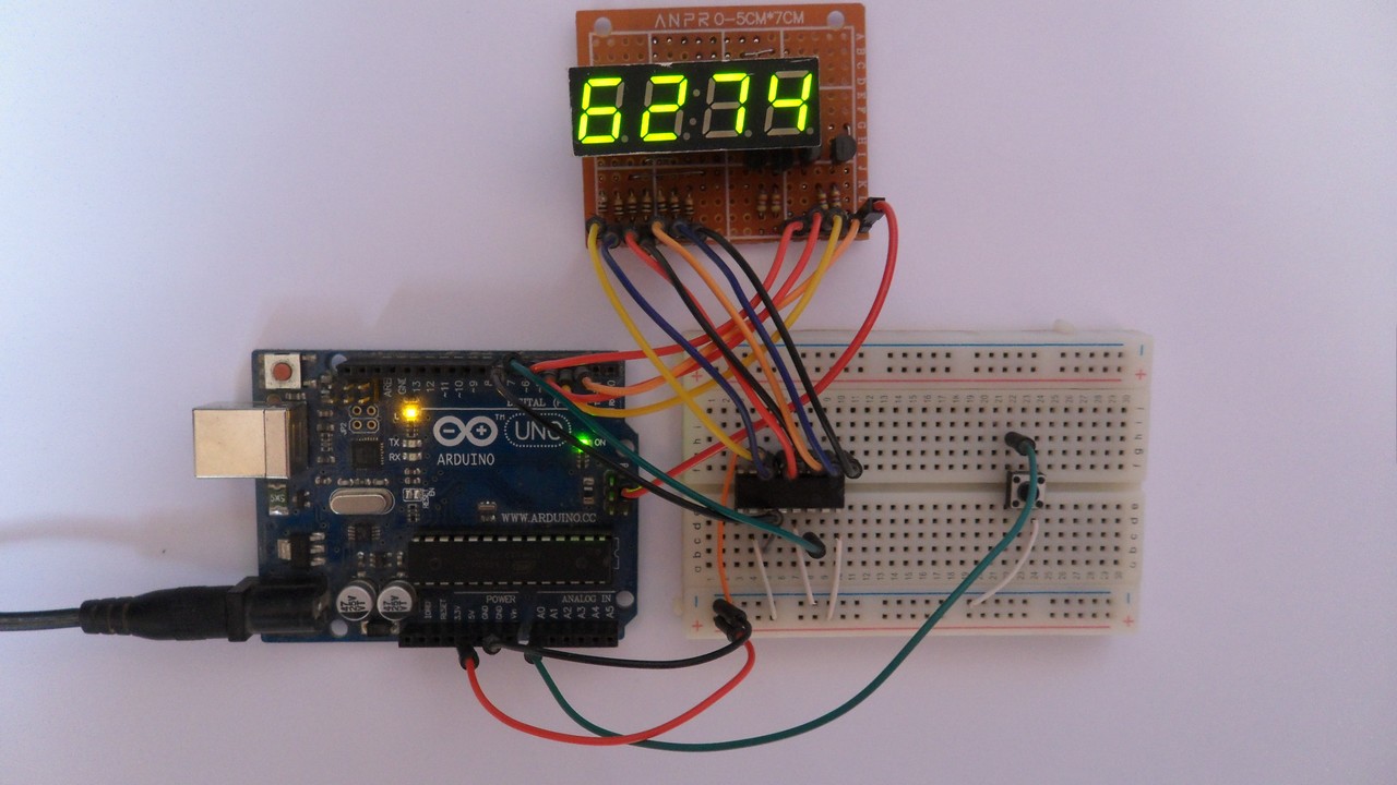
This post shows how to build a simple digital counter using Arduino, common anode 7-segment display with 4 digits, and 74HC595 shift register.
To see how to interface the Arduino with 7-segment display without shift register visit the following post:
Interfacing Arduino with 7-segment display | 4-Digit counter example
Hardware Required:
- Arduino UNO board —> ATMEGA328P datasheet
- 4-Digit common anode 7-segment display
- 74HC595 shift register —-> datasheet
- 4 x PNP transistor (2SA1015, 2S9015, 2N3906 …)
- 8 x 100 ohm resistor
- 4 x 4.7k ohm resistor
- Push button
- Breadboard
- Jumper wires
Arduino 7-Segment display with 74HC595 shift register circuit:
The image below shows our example circuit schematic diagram. Most wire connection is between the 4-digit 7-segment display module and the serial-in parallel-out shift register 74HC595.
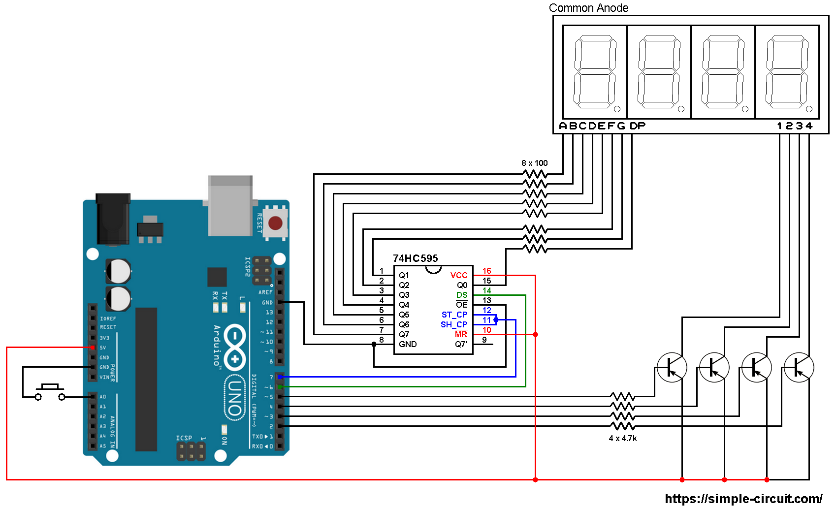
As shown in the circuit diagram above, all segment pins are connected to the 74HC595 output pins, each one through 100 ohm resistor, where:
Segment A … G are connected to 74HC595 pin Q7 … Q1 respectively and segment DP is connected to pin Q0.
The data pin of the 74HC595 shift register is named DS (#14) and it is connected to Arduino pin 6.
ST_CP (or RCLK) and SH_CP (or SRCLK) are connected together which then connected to Arduino pin 7. This is the clock pin.
Since the display has 4 digits there’re 4 common pins: 1 (most left), 2, 3 and 4. Each common pin is connected to collector terminal of one transistor. Emitter terminals of the 4 transistors are connected to +5V which comes from the Arduino board. Base terminals of the four transistors are connected to Arduino through 4.7k resistors.
The 4 transistors are of the same type (PNP).
The push button which is connected to Arduino analog pin 0 (A0) is used to increment the displayed number.
7-Segment display with 74HC595 shift register code:
The Arduino code below doesn’t use any library for the 7-segment display.
The button connection is defined in the code as:
1 2 | // counter button definition #define button A0 |
Shift register clock pin and data pin are defined as:
1 2 3 | // shift register pin definitions #define clockPin 7 // clock pin #define dataPin 6 // data pin |
The display needs to be refreshed periodically, for that I used Timer1 module interrupt with the following configuration:
1 2 3 4 5 | // Timer1 module overflow interrupt configuration TCCR1A = 0; TCCR1B = 1; // enable Timer1 with prescaler = 1 ( 16 ticks each 1 µs) TCNT1 = 0; // set Timer1 preload value to 0 (reset) TIMSK1 = 1; // enable Timer1 overflow interrupt |
With Timer1 prescaler = 1, we’ve an interrupt every 4096 microseconds. That means every digit is displayed for 4096 us. { 4096 us = 65536 / (16 * prescaler) }
Note that Timer1 module is 16-bit timer and Arduino clock frequency is 16MHz.
Functions used in the code:
ISR(TIMER1_OVF_vect) : is Timer1 interrupt function, when the microcontroller interrupted by Timer1 it will directly execute this ‘function’.
void disp(byte number, bool dec_point = 0) : this function is for printing data on the 7-segment display, it prints the variable number which may vary between 0 and 9. The variable dec_point decides whether the DP will be printed or not, the default value is 0 (don’t print), if dec_point = 1 the DP segment will be ON.
void disp_off() : this function turns off the whole display.
I used Arduino shiftOut function (built-in) to send data serially to the 74HC595 shift register.
Full Arduino code:
1 2 3 4 5 6 7 8 9 10 11 12 13 14 15 16 17 18 19 20 21 22 23 24 25 26 27 28 29 30 31 32 33 34 35 36 37 38 39 40 41 42 43 44 45 46 47 48 49 50 51 52 53 54 55 56 57 58 59 60 61 62 63 64 65 66 67 68 69 70 71 72 73 74 75 76 77 78 79 80 81 82 83 84 85 86 87 88 89 90 91 92 93 94 95 96 97 98 99 100 101 102 103 104 105 106 107 108 109 110 111 112 113 114 115 116 117 118 119 120 121 122 123 124 125 126 127 128 129 130 131 132 133 134 135 136 137 138 139 140 141 142 143 144 145 146 147 148 149 150 151 152 153 154 155 156 157 158 159 160 | /* * 7-segment display with 74HC595 shift register * 4-Digit counter example. * Common anode 7-segment display is used. * This is a free software with NO WARRANTY. * https://simple-circuit.com/ */ // counter button definition #define button A0 // shift register pin definitions #define clockPin 7 // clock pin #define dataPin 6 // data pin // common pins of the four digits definitions #define Dig1 5 #define Dig2 4 #define Dig3 3 #define Dig4 2 // variable declarations byte current_digit; int count = 0; void disp(byte number, bool dec_point = 0); void setup() { pinMode(button, INPUT_PULLUP); pinMode(Dig1, OUTPUT); pinMode(Dig2, OUTPUT); pinMode(Dig3, OUTPUT); pinMode(Dig4, OUTPUT); pinMode(clockPin, OUTPUT); pinMode(dataPin, OUTPUT); disp_off(); // turn off the display // Timer1 module overflow interrupt configuration TCCR1A = 0; TCCR1B = 1; // enable Timer1 with prescaler = 1 ( 16 ticks each 1 µs) TCNT1 = 0; // set Timer1 preload value to 0 (reset) TIMSK1 = 1; // enable Timer1 overflow interrupt } ISR(TIMER1_OVF_vect) // Timer1 interrupt service routine (ISR) { disp_off(); // turn off the display switch (current_digit) { case 1: disp(count / 1000); // prepare to display digit 1 (most left) digitalWrite(Dig1, LOW); // turn on digit 1 break; case 2: disp( (count / 100) % 10 ); // prepare to display digit 2 digitalWrite(Dig2, LOW); // turn on digit 2 break; case 3: disp( (count / 10) % 10 ); // prepare to display digit 3 digitalWrite(Dig3, LOW); // turn on digit 3 break; case 4: disp(count % 10); // prepare to display digit 4 (most right) digitalWrite(Dig4, LOW); // turn on digit 4 } current_digit = (current_digit % 4) + 1; } // main loop void loop() { if(digitalRead(button) == 0) { count++; // increment 'count' by 1 if(count > 9999) count = 0; delay(200); // wait 200 milliseconds } } void disp(byte number, bool dec_point) { switch (number) { case 0: // print 0 shiftOut(dataPin, clockPin, MSBFIRST, 0x02 | !dec_point); digitalWrite(clockPin, HIGH); digitalWrite(clockPin, LOW); break; case 1: // print 1 shiftOut(dataPin, clockPin, MSBFIRST, 0x9E | !dec_point); digitalWrite(clockPin, HIGH); digitalWrite(clockPin, LOW); break; case 2: // print 2 shiftOut(dataPin, clockPin, MSBFIRST, 0x24 | !dec_point); digitalWrite(clockPin, HIGH); digitalWrite(clockPin, LOW); break; case 3: // print 3 shiftOut(dataPin, clockPin, MSBFIRST, 0x0C | !dec_point); digitalWrite(clockPin, HIGH); digitalWrite(clockPin, LOW); break; case 4: // print 4 shiftOut(dataPin, clockPin, MSBFIRST, 0x98 | !dec_point); digitalWrite(clockPin, HIGH); digitalWrite(clockPin, LOW); break; case 5: // print 5 shiftOut(dataPin, clockPin, MSBFIRST, 0x48 | !dec_point); digitalWrite(clockPin, HIGH); digitalWrite(clockPin, LOW); break; case 6: // print 6 shiftOut(dataPin, clockPin, MSBFIRST, 0x40 | !dec_point); digitalWrite(clockPin, HIGH); digitalWrite(clockPin, LOW); break; case 7: // print 7 shiftOut(dataPin, clockPin, MSBFIRST, 0x1E | !dec_point); digitalWrite(clockPin, HIGH); digitalWrite(clockPin, LOW); break; case 8: // print 8 shiftOut(dataPin, clockPin, MSBFIRST, !dec_point); digitalWrite(clockPin, HIGH); digitalWrite(clockPin, LOW); break; case 9: // print 9 shiftOut(dataPin, clockPin, MSBFIRST, 0x08 | !dec_point); digitalWrite(clockPin, HIGH); digitalWrite(clockPin, LOW); } } void disp_off() { digitalWrite(Dig1, HIGH); digitalWrite(Dig2, HIGH); digitalWrite(Dig3, HIGH); digitalWrite(Dig4, HIGH); } // end of code. |
The result of this example should be the same as the one shown in the following video (4-digit counter without shift register):


Line 72 : current_digit = (current_digit % 4) + 1;
Please could you explain the function of this line?
I WAS TRY MAKE IS ON PROTEUS BUT ITS NOT WORKING. AND ALL DIG IS ON AND THEY NOT SHOWING NUMBERS.
I RECONTROL ALL WIRES BUT NOTHING CHANGE.
74hc595 is not used in video ,it is directly connected to Arduino board.this code is applicable to with out 74HC595.
Hi .Nice code .If more segments needs to be added , refresh frequency has to be increased . i’ve needed to use two 4-digit 7-segment displays with code corrections ,with ADC MCP3424 ,voltmetter and ammeter . In code digits from 5 to 8 and dots control added . With current timer1 code ,visible digits flashing occured , had no luck of increasing refresh frequency . So used http://www.8bit-era.cz/arduino-timer-interrupts-calculator.html this calculator, TIMER2 code part, with frequency 2000 Hz . 4000 Hz is more than enough .
can u give us common cathode clock values 7 values from 0 to 9 case of this project please ????
Please edit
can u give us common cathode clock values 7 values from 0 to 9 case of this project please