This post shows how to interface Arduino UNO board with 7-segment display in order to build a simple 4-digit counter which counts from 0 to 9999. A push button connected to Arduino is used to increment the displayed number.
There are two types of the seven-segment displays: common anode and common cathode.
In the common anode type all the 7 LED anode terminals are connected together whereas in the common cathode all cathode terminals are connected together.
The common terminal is connected to +VCC (+5V, +3.3V …) or GND (0V) depending on the type of the 7-segment display (common anode or common cathode respectively).
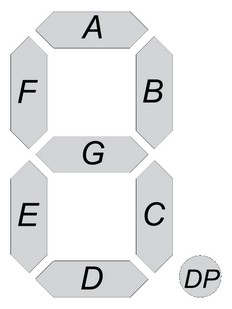
Basically for each 7-segment digit there are 8 pins: one for the common terminal (anode or cathode) and 7 pins for the 7 segments (A, B, C, D, E, F and G). Another pin may be used for the decimal point (DP).
In multi-digit 7-segment display (for example 4-digit) all pins of the same segment are connected together (segment A of digit 1 with segment A of digit 2 …), and each digit has its common pin alone. This is called multiplexing technique. This technique minimizes number of pins used.
So for a 4-digit display we’ll have 7 pins of the 7 segments, 4 pins of the 4 digits (common terminals) and 1 pin for the decimal point (DP) which means a total of 12 pins.
Hardware Required:
- Arduino UNO board
- 4-Digit common anode 7-segment display
- 4 x PNP transistor (2SA1015, 2S9015, 2N3906 …)
- 7 x 100 ohm resistor
- 4 x 4.7k ohm resistor
- Push button
- Breadboard
- Jumper wires
Interfacing Arduino with 7-segment display circuit:
Example circuit schematic diagram is shown below.
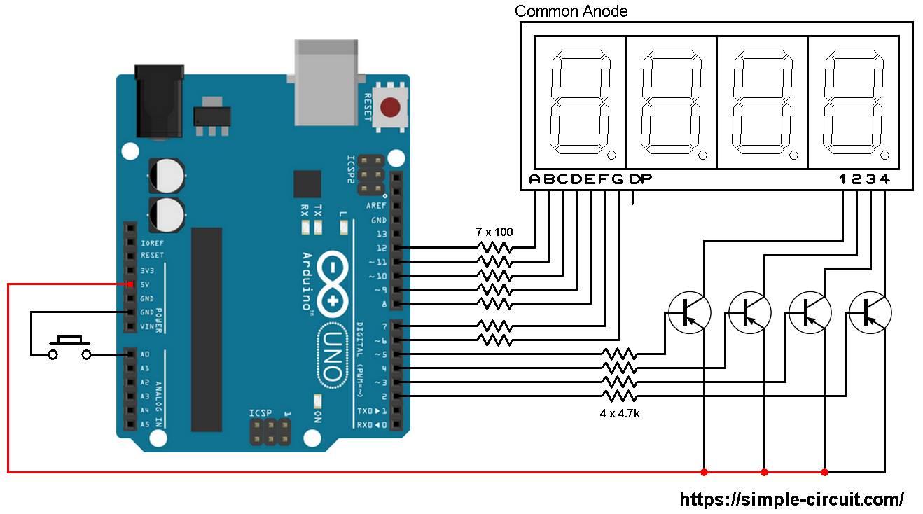
The push button which is connected to Arduino A0 pin is used to increment the displayed number.
A common anode 7-segment display is used in this example.
In the circuit there are 4 transistors of the type PNP, the collector of each transistor is connected to common anode pin of 1 digit. That means each transistor supplies one digit segments.
The 4 transistors are used to supply the display LEDs with sufficient current because Arduino microcontroller (ATmega328P) may not be able to do that (maximum output current is 40mA).
Each transistor emitter pin is connected to +5V that comes from the Arduino board and each transistor base is connected to the Arduino through 4.7k resistor.
Each 100 ohm resistor is used for limiting the current that passes through the segment LED.
Interfacing Arduino with 7-segment display code:
Example Arduino code is below.
Since the 4 digits are multiplexed we need to refresh the display very quickly (display one digit at a time, others are off). For that I used Timer1 module interrupt with the following configuration:
1 2 3 4 5 | // Timer1 module overflow interrupt configuration TCCR1A = 0; TCCR1B = 1; // enable Timer1 with prescaler = 1 ( 16 ticks each 1 µs) TCNT1 = 0; // set Timer1 preload value to 0 (reset) TIMSK1 = 1; // enable Timer1 overflow interrupt |
With the above configuration Timer1 module overflows every 4096 microseconds (4096 = 65536/16) which is a good refresh period.
Note that Timer1 module is 16-bit timer, prescaler = 1 (TCCR1B = 1) and Arduino UNO clock = 16MHz.
1 2 3 4 5 6 7 8 9 10 11 12 13 14 15 16 17 18 19 20 21 22 23 24 25 26 27 28 29 30 31 32 33 34 35 36 37 38 39 40 41 42 43 44 45 46 47 48 49 50 51 52 53 54 55 56 57 58 59 60 61 62 63 64 65 66 67 68 69 70 71 72 73 74 75 76 77 78 79 80 81 82 83 84 85 86 87 88 89 90 91 92 93 94 95 96 97 98 99 100 101 102 103 104 105 106 107 108 109 110 111 112 113 114 115 116 117 118 119 120 121 122 123 124 125 126 127 128 129 130 131 132 133 134 135 136 137 138 139 140 141 142 143 144 145 146 147 148 149 150 151 152 153 154 155 156 157 158 159 160 161 162 163 164 165 166 167 168 169 170 171 172 173 174 175 176 177 178 179 180 181 182 183 184 185 186 187 188 189 190 191 192 193 194 195 196 197 198 199 200 201 202 203 204 205 206 207 208 | /* * Interfacing Arduino with common anode 7-segment display * 4-Digit counter example. * This is a free software with NO WARRANTY. * http://simple-circuit.com/ */ // counter button definition #define button A0 // segment pin definitions #define SegA 12 #define SegB 11 #define SegC 10 #define SegD 9 #define SegE 8 #define SegF 7 #define SegG 6 // common pins of the four digits definitions #define Dig1 5 #define Dig2 4 #define Dig3 3 #define Dig4 2 // variable declarations byte current_digit; int count = 0; void setup() { pinMode(button, INPUT_PULLUP); pinMode(SegA, OUTPUT); pinMode(SegB, OUTPUT); pinMode(SegC, OUTPUT); pinMode(SegD, OUTPUT); pinMode(SegE, OUTPUT); pinMode(SegF, OUTPUT); pinMode(SegG, OUTPUT); pinMode(Dig1, OUTPUT); pinMode(Dig2, OUTPUT); pinMode(Dig3, OUTPUT); pinMode(Dig4, OUTPUT); disp_off(); // turn off the display // Timer1 module overflow interrupt configuration TCCR1A = 0; TCCR1B = 1; // enable Timer1 with prescaler = 1 ( 16 ticks each 1 µs) TCNT1 = 0; // set Timer1 preload value to 0 (reset) TIMSK1 = 1; // enable Timer1 overflow interrupt } ISR(TIMER1_OVF_vect) // Timer1 interrupt service routine (ISR) { disp_off(); // turn off the display switch (current_digit) { case 1: disp(count / 1000); // prepare to display digit 1 (most left) digitalWrite(Dig1, LOW); // turn on digit 1 break; case 2: disp( (count / 100) % 10); // prepare to display digit 2 digitalWrite(Dig2, LOW); // turn on digit 2 break; case 3: disp( (count / 10) % 10); // prepare to display digit 3 digitalWrite(Dig3, LOW); // turn on digit 3 break; case 4: disp(count % 10); // prepare to display digit 4 (most right) digitalWrite(Dig4, LOW); // turn on digit 4 } current_digit = (current_digit % 4) + 1; } // main loop void loop() { if(digitalRead(button) == 0) { count++; // increment 'count' by 1 if(count >: 9999) count = 0; delay(200); // wait 200 milliseconds } } void disp(byte number) { switch (number) { case 0: // print 0 digitalWrite(SegA, LOW); digitalWrite(SegB, LOW); digitalWrite(SegC, LOW); digitalWrite(SegD, LOW); digitalWrite(SegE, LOW); digitalWrite(SegF, LOW); digitalWrite(SegG, HIGH); break; case 1: // print 1 digitalWrite(SegA, HIGH); digitalWrite(SegB, LOW); digitalWrite(SegC, LOW); digitalWrite(SegD, HIGH); digitalWrite(SegE, HIGH); digitalWrite(SegF, HIGH); digitalWrite(SegG, HIGH); break; case 2: // print 2 digitalWrite(SegA, LOW); digitalWrite(SegB, LOW); digitalWrite(SegC, HIGH); digitalWrite(SegD, LOW); digitalWrite(SegE, LOW); digitalWrite(SegF, HIGH); digitalWrite(SegG, LOW); break; case 3: // print 3 digitalWrite(SegA, LOW); digitalWrite(SegB, LOW); digitalWrite(SegC, LOW); digitalWrite(SegD, LOW); digitalWrite(SegE, HIGH); digitalWrite(SegF, HIGH); digitalWrite(SegG, LOW); break; case 4: // print 4 digitalWrite(SegA, HIGH); digitalWrite(SegB, LOW); digitalWrite(SegC, LOW); digitalWrite(SegD, HIGH); digitalWrite(SegE, HIGH); digitalWrite(SegF, LOW); digitalWrite(SegG, LOW); break; case 5: // print 5 digitalWrite(SegA, LOW); digitalWrite(SegB, HIGH); digitalWrite(SegC, LOW); digitalWrite(SegD, LOW); digitalWrite(SegE, HIGH); digitalWrite(SegF, LOW); digitalWrite(SegG, LOW); break; case 6: // print 6 digitalWrite(SegA, LOW); digitalWrite(SegB, HIGH); digitalWrite(SegC, LOW); digitalWrite(SegD, LOW); digitalWrite(SegE, LOW); digitalWrite(SegF, LOW); digitalWrite(SegG, LOW); break; case 7: // print 7 digitalWrite(SegA, LOW); digitalWrite(SegB, LOW); digitalWrite(SegC, LOW); digitalWrite(SegD, HIGH); digitalWrite(SegE, HIGH); digitalWrite(SegF, HIGH); digitalWrite(SegG, HIGH); break; case 8: // print 8 digitalWrite(SegA, LOW); digitalWrite(SegB, LOW); digitalWrite(SegC, LOW); digitalWrite(SegD, LOW); digitalWrite(SegE, LOW); digitalWrite(SegF, LOW); digitalWrite(SegG, LOW); break; case 9: // print 9 digitalWrite(SegA, LOW); digitalWrite(SegB, LOW); digitalWrite(SegC, LOW); digitalWrite(SegD, LOW); digitalWrite(SegE, HIGH); digitalWrite(SegF, LOW); digitalWrite(SegG, LOW); } } void disp_off() { digitalWrite(Dig1, HIGH); digitalWrite(Dig2, HIGH); digitalWrite(Dig3, HIGH); digitalWrite(Dig4, HIGH); } // end of code. |
The following video shows a simple protoboard circuit of the example:
and the video below shows Proteus simulation (simulation circuit is not the same as real hardware circuit, example circuit diagram is shown above):
Proteus simulation file download:
Arduino 7-segment display counter
Other Arduino projects where 7-segment display was used:
Print Arduino ADC values on 7-segment display
Arduino with rotary encoder and 7 segment display
Arduino with LM335 temperature sensor and seven-segment display
Interfacing Arduino with LM35 sensor and 7-segment display
7-Segment display with 74HC595 shift register | Arduino Projects


Hi guys,
I have tried to upload the code and this error code popped up. If anybody knows how to fix it that would be great.
sketch_feb08a:82:17: error: expected ‘)’ before ‘:’ token
if(count >: 9999)
‘gt’ was not declared in this scope
This code can’t be verified as the disp_off(); hasn’t been defined. I’d offer up more information but I’m not entirely sure as to what it means.
I have gotten past this now but I am struggling to get the button to increment the counter. I have adjusted the code for a common cathode display, with NPN and grounding instead of pulling up to 5V but I’m still missing something to get the button to have any effect.
If you are using the example code from this project, and using serial.parseint() to supply the value for ‘count’, it should work. You should be able to read and display values from 0 to 9999. If you share your code, someone might be able to identify why it isn’t functioning as expected.
Hi, can anyone tell me how to take any number input from the user and display that on the 7 segment 4 number display? I used serial.parseint(), but its not showing the digits in the tens, hundredths and the thousandths place.
In this example to show 2056 on the display we need <= 2055 button presses.
Can another switch be added to select the digits(ones tens hundreds and thousands and the increment the number on each digit. The number will increase upto 9 and roll over to 0 but will not go to next digit.
Yes you can do that, but you’ve to make some modifications to the code!
Any suggestions for setting a prescaler for 2048us and 1024us in use as PWM?
Hi,
Why are we taking pnp transistor and not npn?
Basically, choosing a transistor type of NPN or PNP depends on circuit design. In this project we’ve a common anode 7-segment display. This means each common pin has to be connected to +5V in order to turn on its related digit.
The NPN transistor type allows current flows from collector to emitter when base-emitter voltage is greater than threshold voltage (about 0.7V).
The PNP transistor allows current flows from collector to emitter when base-emitter voltage is lower than threshold voltage (about -0.7V).
In this project if we use a NPN type then its collector will be connected to +5V and its emitter to the common pin of 7-segment display. Normally, the NPN transistor turns on when the Arduino outputs logic high (+5V). If there’s a 5V at base and 5V at emitter how will the transistor turn on?
You can use NPN type but the 7-segment display will not be supplied correctly with 5V (about 4 Volts) which yields low brightness.
If you have a common cathode 7-segment display then you should use NPN type.
You are correct. There is a mistake in circuit diagram.
Good day,
How was the base resistor value of 4.7k calculated?
count++; // increment ‘count’ by 1
if(count > 9999)
count = 0;
delay(200);
if(count > 9999)
Thank you I got it fixed as you said.
thank you i got, not easy
how to add reset thanks?
how this can turn in to a 5 digit display