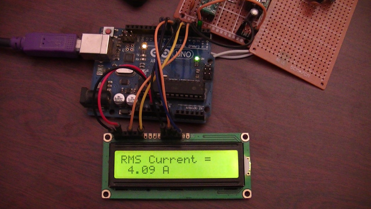
This project shows how to simply measure AC current using an Arduino uno board and 50/5 current transformer with Ture RMS calculations.
A 1602 LCD connected to the Arduino board is used to display current values, the Arduino also sends the same values to the Laptop which can be viewed using serial monitor.
Hints:
No warranty is provided with this project, so do it at your own risk!
A part of project circuit may be subjected to high voltage which is very harmful to human body, so be-careful!
Abbreviations:
AC: Alternating Current
DC: Direct Current
TRMS: True Root Mean Square
ADC: Analog-to-Digital Converter
CT: Current Transformer
LDO Regulator: Low Dropout Regulator
PCB: Printed Circuit Board
DIY: Do It Yourself
About Current Transformer:
Current transformer (CT) is an instrument transformer which is used to step down current by the inverse of its turns ratio. The secondary of the current transformer has more tuns than the primary. Today, a typical CT secondary rated current is 5A or 1A, however, many CTs have smaller rated secondary current such as 20mA, 40mA …
Generally, current transformer is used to transmit current image information signal to a measuring instrument, protective device or similar apparatus.
Usually, the current transformer ratio is stated to include primary and secondary current ratings, for example 600:5, means that a 600A in the primary is converted into 5A in the secondary.
When current is passing through the primary of the CT, the secondary should be always kept shorted either through a shunt resistor (or meter coils) or through a shorting switch (for example jumper) because the secondary may produce very high and harmful potential.
Another thing should be noted with CT is its rated apparent power, for example 10VA, or its maximum burden impedance.
AC Current measurement using Arduino and current transformer circuit:
Project circuit diagram is shown below (click on the image for full view).
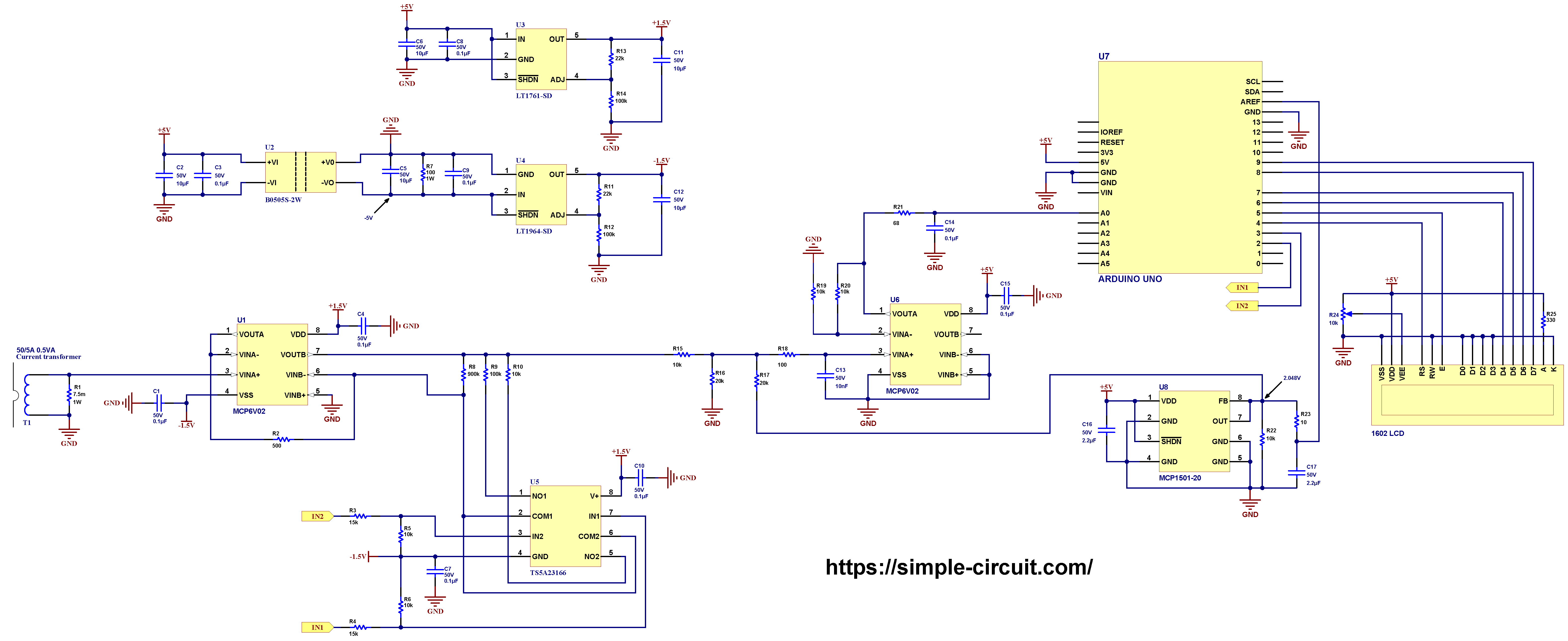
Note that in the circuit there is 1 ground only which is the same as the Arduino ground (GND).
The Arduino uno board is represented by U7.
For circuit resistors, a low tolerance resistors should be used, let’s say 1% or lower, lower tolerance gives better accuracy!
Hardware required:
This is a summary of circuit required parts (circuit schematic diagram may contain some component parameters not mentioned below).
- Arduino Uno or equivalent board such as Arduino Nano
- 50/5A current transformer
- 2 x MCP6V02 op amp (U1, U6) —> details
- MCP1501-20 buffered voltage reference (U8) —> details
- TS5A23166 dual analog switch (U5) —> details
- LT1761-SD LDO regulator (U3) —> details
- LT1964-SD LDO negative regulator (U4) —> details
- B0505S-2W isolated DC-DC converter (U2)
- 1602 LCD screen
- 7.5 milliohm Shunt resistor (R1)
- 900k resistor (R8)
- 3 x 100k resistor (R9, R12, R14)
- 2 x 22k resistor (R11, R13)
- 2 x 20k resistor (R16, R17)
- 2 x 15k resistor (R3, R4)
- 7 x 10k resistor (R5, R6, R10, R15, R19, R20, R22)
- 500 Ohm resistor (R2)
- 330 Ohm resistor (R25)
- 2 x 100 Ohm resistor (R7, R18)
- 68 Ohm resistor (R21)
- 10 Ohm resistor (R23)
- 10k variable resistor (R24)
- 5 x 10 µF capacitor (C2, C5, C6, C11, C12)
- 2 x 2.2 µF capacitor (C16, C17)
- 9 x 0.1 µF capacitor (C1, C3, C4, C7, C8, C9, C10, C14, C15)
- 10 nF capacitor (C13)
Circuit description:
As shown in project circuit schematic diagram above, the current transformer which is noted as T1 has the following characteristics:
Primary rated current: 50A
Secondary rated current: 5A
Turns ratio: 50/5 = 10
Apparent power: 0.5VA (other CT with higher power can also be used)
The full name of the current transformer which I’m using is: BZCT18AL, it’s the one shown below:
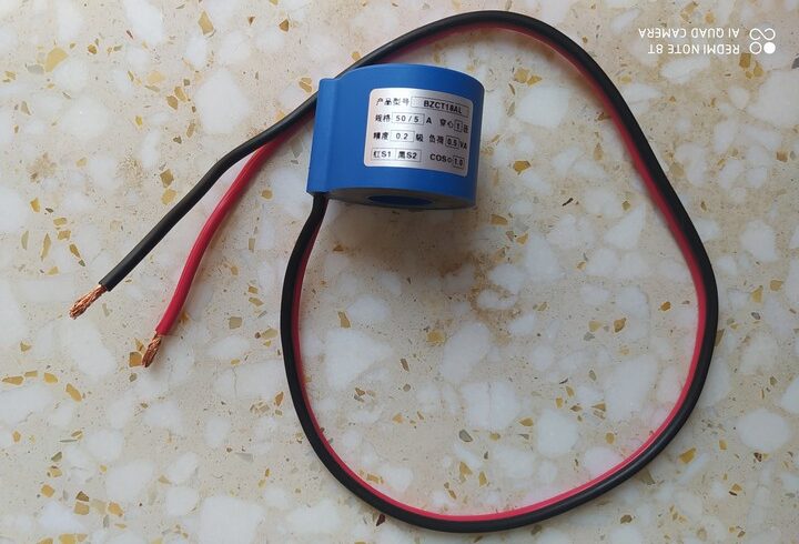
The wire that feeds the load passes through the hole of the current transformer. Note that only 1 wire of a single phase load has to be used to measure the current, the CT will read 0A if the two wires (phase and natural) are used because the sum of the magnetic field produced by the 2 wires is 0!
Other types of current transformers may be used such as 20/5, 75/5, 100/5 … but its ratio needs to be modified in the Arduino code.
The secondary coil of the current transformer is connected to a shunt resistor of 7.5 milliohms (0.0075 Ohm) with rated current of 10 Amps. Other resistance value of the shunt resistor may be used but it depends on the apparent power the CT can produce. For a 0.5VA we can use shunt resistor with resistance up to 20 milliohms (0.5VA = 0.02 x 5² where 5 is CT rated secondary current) and for a 1VA we can use up to 40 milliohms (neglecting other losses such as wire losses). For better accuracy a low resistance should be used.
The full name of the shunt resistor which I used in this project is: FL-2C 10A/75mV, it is shown in the image below. Its current carrying capacity is 10 Amps with voltage drop of 75 milliVolts. By applying Ohm’s law, this shunt resistor has a resistance of 75/10 = 7.5 millohms.
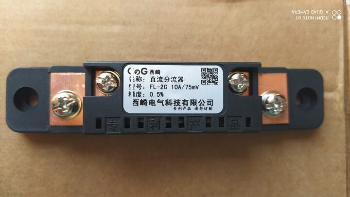
Current carrying capacity of the shunt resistor has to be taken into consideration, rated power also may be used with this formula: P = R x I² , where R is the resistance and I is CT secondary rated current.
Because of very low voltage drop across the shunt resistor, installation method may have a big affect on the overall accuracy of the measurement device, always we should go to the used shunt resistor datasheet to see how to place it on the PCB (Printed Circuit Board).
I used the FL-2C 10A/75mV because it has a good accuracy of 0.5% (as noted), low cost and easy to use for a DIY project.
So, for a 5 Amp (rated CT secondary) passing through the shunt resistor, a voltage drop of 37.5 mV is generated. One terminal of the shunt resistor is connected to circuit ground (GND) and the other one is connected to MCP6V02 auto-zeroed rail-to-rail op amp (U1 in the circuit schematic). I used this type op amps because they have very low voltage offset & drift and input bias current, they are really good choice for this kind of projects when it is related to accuracy.
The MCP6V02 (U1) from Microchip contains 2 independent op amps in one package. The first one is used as a voltage follower where its output is similar to its input which is the voltage signal across the shunt resistor. The input impedance of the voltage follower is very big which has no effect on the voltage across the shunt resistor.
The second op amp of the MCP6V02 (U1) is used to amplify the voltage signal produced by the voltage follower with variable gain, the type of this amplifier is inverting amplifier.
I used an amplifier circuit in order to amplify the very low voltage signal that the Arduino may not be able to read. The gain of this amplifier is automatically controlled by the Arduino with gains of: 18, 180 and 1800.
To easily control the amplifier gain I used TS5A23166 analog switch from Texas Instruments. This analog switch has an ON resistance of 0.9 Ohm which can be ignored when it compared with 100k or 10k. The TS5A23166 chip contains two analog switches.
The first switch is closed (NO1 is connected to COM1) by sending a logic high to IN1 pin, and the second switch is closed (NO2 is connected to COM2) by sending a logic high to IN2 pin.
The digital control signals IN1 and IN2 are sent from pins 2 and 3 of the Arduino uno board, respectively.
The following schematic should simplify the circuit described above where the MCP6V02 (U1) is represented by 2 op amps and the TS5A23166 (U5) is represented by 2 switches S1 & S2:
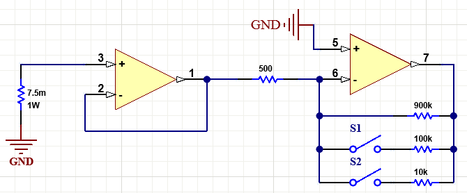
With the two switches open, the gain of the inverting amplifier is equal to: 900k/0.5k = 1800. When switch S1 closed the gain becomes: (900k // 100k)/0.5k = 90k/0.5k = 180. If both switches are closed then the gain is: (900k // 100k // 10k)/0.5k = 9k/0.5k = 18.
If you don’t have 500 Ohm resistor (R2) then you can use two 1k in parallel, the same thing for 900k resistor (R8) where we can get it by connecting two 1.8M in parallel.
Both MCP6V02 (U1) and TS5A23166 (U5) are supplied with dual bipolar power supply with +1.5V and -1.5V. Such supply is required for both ICs because the input is an AC signal, if single supply is used then the negative part of the signal waveform will be ‘killed’!
I used LT1761-SD LDO regulator (U3) from Analog Devices to get approximately +1.5V, the input voltage of this regulator is 5V and it comes from the Arduino board, I chose R13 and R14 (connected to ADJ pin) respectively with values 22k and 100k to get an output of +1.5V (voltage output equation in LT1761 datasheet).
In the other hand, I used LT1964-SD LDO negative regulator (U4) from Analog Devices to get approximately -1.5V, the input voltage of this regulator is -5V. I chose R11 and R12 (connected to ADJ pin) respectively with values 22k and 100k to get an output of -1.5V (voltage output equation in LT1964 datasheet).
However, to get -5V I used B0505S-2W isolated DC/DC converter (U2). The input as well as the output of this small module is 5V, with the input isolated from the output.
By connecting B0505S-2W output positive pin to circuit GND we get -5V on its negative pin (with respect to circuit GND). The negative voltage is then used to feed the LT1964-SD regulator.
The B0505S-2W input supply is from the Arduino board.
Since we are working with alternating current then a part of its waveform is negative. The Arduino ADC module can’t read analog negative voltages and we need to shift all the waveform to the positive side, this means we have to add a dc offset to the AC voltage signal produced by the MCP6V02 (U1) without affecting the gain again.
For that I used another amplifier circuit which firstly filters the signal and secondly adds a dc offset of 1.024V. The main component is another MCP6V02 (U6) where just 1 op amp is used. It is supplied with 5V from the Arduino board (pin 8 of U6 is connected to Arduino 5V pin, and pin 4 of U6 is connected to any of Arduino GND pins).
This circuit has a gain of 1 and dc offset of 1.024V.
For the U6 IC and instead of MCP6V02, other op amp ICs may be used for example: MCP6022 (or MCP6021), MCP6062 (or MCP6061) …
Before the AC signal goes to Arduino analog channel 0 (A0) it passes through an RC low pass filter which comprised of R21 and C14. The frequency of this filter can be simply calculated with this equation:
f = 1/(2 x π x R x C) = 23.4kHz
I used the MCP1501-20 (U8) to get a precise voltage of 2.048V which is then used as positive voltage reference for the Arduino microcontroller ADC module. The MCP1501-20 is also supplied from the Arduino board with 5V. Its output is filtered and connected to the Arduino AREF pin.
The 1602 LCD screen (2 rows and 16 columns) is used to display the value of the current flows through the current transformer (load current), it is connected to the Arduino board as follows:
RS —> Arduino digital pin 4
E —> Arduino digital pin 5
D4 —> Arduino digital pin 6
D5 —> Arduino digital pin 7
D6 —> Arduino digital pin 8
D7 —> Arduino digital pin 9
VSS, RW, D0, D1, D2, D3 and K are connected to GND,
VEE to the 10k Ohms variable resistor (or potentiometer) output,
VDD to Arduino 5V and A to Arduino 5V through 330 ohm resistor.
VEE pin is used to control the contrast of the LCD. A (anode) and K (cathode) are the back light LED pins.
AC Current measurement using Arduino and current transformer code:
Project code is the one below, it was tested with Arduino Uno board.
The code tries to calculate RMS values for symmetrical AC signal applied to analog channel 0. It can measure AC currents only, when a DC current follows through the shunt resistor then the display will show 0.00 A, because at all times the DC (or average) value is deducted from the whole input signal.
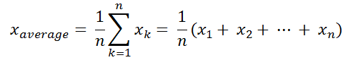
Simply the average (mean or DC offset) value in discrete-time is the sum of all sample values divided by number of samples:
And the RMS value in discrete-time can be calculated using the following equation:

The Arduino uno board microcontroller (ATmega328P) contains a 10-bit ADC module, the positive voltage reference is 2.048V means that a 2.048V is digitally represented by 1023 and 0V is represented by 0 (1 digit for every 2mV).
The Arduino automatically switches between the three gain choices (18, 180 and 1800) whenever the RMS voltage applied to analog channel 0 exceeds 600mV or goes down under 60mV. If the voltage goes above 600mV then the Arduino decreases the gain by closing gain control switches, and if the voltage goes below 60mV then the Arduino increases the gain by opening gain control switches.
A 600mV corresponds to load current of 0.444 A and 4.44 A respectively for gain of 1800 and 180, and a 60mV corresponds to load current of 4.44 A and 0.444 A respectively for gain of 18 and 180.
Load current ranges with respect to gain are as follows:
| Gain | Load current range (A) |
| 1800 | 0 – 0.444 |
| 180 | 0.444 – 4.44 |
| 18 | 4.44 – 50 |
Full Arduino code:
1 2 3 4 5 6 7 8 9 10 11 12 13 14 15 16 17 18 19 20 21 22 23 24 25 26 27 28 29 30 31 32 33 34 35 36 37 38 39 40 41 42 43 44 45 46 47 48 49 50 51 52 53 54 55 56 57 58 59 60 61 62 63 64 65 66 67 68 69 70 71 72 73 74 75 76 77 78 79 80 81 82 83 84 85 86 87 88 89 90 91 92 93 94 95 96 97 98 99 100 101 102 103 104 105 106 107 108 109 110 111 112 113 114 115 116 117 118 119 120 121 122 123 124 | /************************************************************************ * * AC Current measurement with Arduino and current transformer. * Calculated RMS current values are printed on 1602 LCD screen and serial monitor. * This is a free software with NO WARRANTY - Use it at your own risk! * http://simple-circuit.com/ * ************************************************************************/ #include <LiquidCrystal.h> // include Arduino LCD library // LCD module connections (RS, E, D4, D5, D6, D7) LiquidCrystal lcd(4, 5, 6, 7, 8, 9); // define analog channel input #define INPUT_CHANNEL A0 // define autoranging control pins #define CH0 2 #define CH1 3 // other definitions #define CT_RATIO 10 // current transformer ratio 50/5 = 10 #define SHUNT_RES 7.5 // shunt resistor connected to CT secondary = 7.5 milli Ohm // variables byte gain; const uint16_t gain_table[3] = {1800, 180, 18}; const uint16_t n = 512; // total number of samples (readings) int16_t r_array[n]; // readings array void setup(void) { Serial.begin(9600); pinMode(CH0, OUTPUT); pinMode(CH1, OUTPUT); lcd.begin(16, 2); // set up the LCD's number of columns and rows lcd.setCursor(0, 0); // move cursor to column 0, row 0 [position (0, 0)] lcd.print("RMS Current ="); gain = 0; gain_set(gain); analogReference(EXTERNAL); // set positive reference voltage to external } void gain_set(uint16_t g) { switch(g) { case 0: digitalWrite(CH0, LOW); digitalWrite(CH1, LOW); break; case 1: digitalWrite(CH0, HIGH); digitalWrite(CH1, LOW); break; case 2: digitalWrite(CH0, HIGH); digitalWrite(CH1, HIGH); } } void loop() { float dc_offset = 0; float rms_voltage = 0; // read voltage at INPUT_CHANNEL 'n' times and save data to 'r_array' for (uint16_t i = 0; i < n; i++) { r_array[i] = analogRead(INPUT_CHANNEL); delayMicroseconds(200); } // calculate signal average (DC offset) for (uint16_t i = 0; i < n; i++) dc_offset += r_array[i]; dc_offset = dc_offset / n; // calculate AC signal RMS value for (uint16_t i = 0; i < n; i++) { rms_voltage += sq( r_array[i] - dc_offset ); } rms_voltage = rms_voltage / n; // calculate Arduino analog channel input RMS voltage in millivolts rms_voltage = 2 * sqrt(rms_voltage); // 2 = 2048/1024 if( rms_voltage > 600.0 && gain < 2 ) { gain++; gain_set(gain); return; } else if ( rms_voltage < 60.0 && gain > 0 ) { gain--; gain_set(gain); return; } // calculate RMS voltage across the shunt resistor in mV (remove op amp gain) rms_voltage /= gain_table[gain]; // calculate current passing through the shunt resistor by applying Ohm's Law (in Amps) float rms_current = rms_voltage / SHUNT_RES; // now we can get current passing through the CT in Amps rms_current = rms_current * CT_RATIO; char _buffer[8]; if(rms_current < 10.0) // if current < 10 Amps sprintf( _buffer, " %1u.%02u A", (uint8_t)rms_current, (uint16_t)(rms_current * 100) % 100 ); else sprintf( _buffer, "%2u.%02u A", (uint8_t)rms_current, (uint16_t)(rms_current * 100) % 100 ); // print data on the LCD lcd.setCursor(0, 1); lcd.print(_buffer); // send data to Arduino serial monitor Serial.print( "RMS Current = " ); Serial.println( _buffer ); Serial.println(); delay(500); } // end of code. |
The video below shows my hardware circuit test with some different loads up to about 10 Amps. I hope the video is clear for you and sorry for bad recording:
Note that some wires connecting the Arduino uno and the DIY PCB are soldered on the back of the two boards, this removes small voltages & noise caused by poor connections between jumper wires and Arduino board female header pins.
Which one is more accurate, the Arduino ammeter or the UNI-T UT219DS clamp meter?
Actually, I’m fully trusting my Arduino ammeter!!


