This post shows how to build a simple auto-ranging ohmmeter using Arduino uno board where resistor value (resistance) is displayed on 16×2 LCD screen and on the laptop through serial monitor software (for example Arduino IDE serial monitor).
Working Principle:
Today, many ohmmeters use voltage divider technique to measure the resistance of an unknown resistor. In this project the same technique also will be used.
Basically, a voltage divider consists of 2 resistors as shown in the following figure:
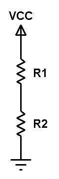
Applying voltage divider equation to the above circuit we get:
Voltage across resistor R1: VR1 = VCC x R1/(R1 + R2)
Voltage across resistor R2: VR2 = VCC x R2/(R1 + R2)
Assume that the resistance of R1 is known and R2 is unknown, by applying voltage divider equation we can easily get the value of R2 by measuring the voltage across it where: R2 = VR2 x R1/(VCC – VR2). If VR2 is equal to VCC then R2 = infinite.
How to measure R2 voltage (VR2):
The voltage is an analog signal and we can measure it using ADC (Analog-to-Digital) converter which converts analog data into digital data. The Arduino board with ATmega328P microcontroller (UNO, Nano, Mini …) has a built-in 10-bit ADC module where VCC (+5V) is represented by 1023 and 0 volts is represented by 0 (if VDD is already used as positive voltage reference).
Do we need fixed voltage reference?
Actually, I think there’s no need for a fixed voltage reference and adding it will not give a big change in the results. Because the voltage divider positive terminal (VCC) and the ADC positive reference voltage are connected to the same point and any change of this point voltage will affect both the voltage divider output and the ADC module.
Multirange ohmmeter:
To get a good value of the resistor to be measured, a multirange ohmmeter should be used.
The multi-range ohmmeter may also use voltage divider technique with different values of resistor R1. The following image shown a simple diagram of multi-range ohmmeter:
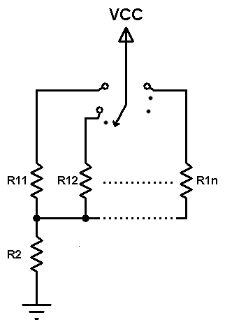
The multi-range ohmmeter is based on a mechanical switching device with 1 input and multi output. At any time just one known resistor (R11, R12 … R1n) is connected in series with the unknown resistor R2.
Auto-ranging ohmmeter:
The auto-range ohmmeter operates the same as the multi-range ohmmeter except that the mechanical switching device is replaced by electronic switches such as transistors driven by an intelligent device (microprocessor, microcontroller …) that decides which switch is closed according to the resistance value of the unknown resistor.
Project Hardware Required:
- Arduino board
- 1602 LCD screen
- 5 x PNP transistor (2SA1015, 2N3906 …)
- 2 x 100nF ceramic capacitor
- 5 x 4.7k ohm resistor
- 2M ohm resisor
- 100k ohm resistor
- 10k ohm resistor
- 1k ohm resistor
- 100 ohm resistor
- 330 ohm resistor
- 10k ohm variable resistor or potentiometer
- Breadboard
- Jumper wires
Arduino autoranging ohmmeter circuit:
Project circuit diagram is shown below.
Note that all the grounded terminals should be connected together.
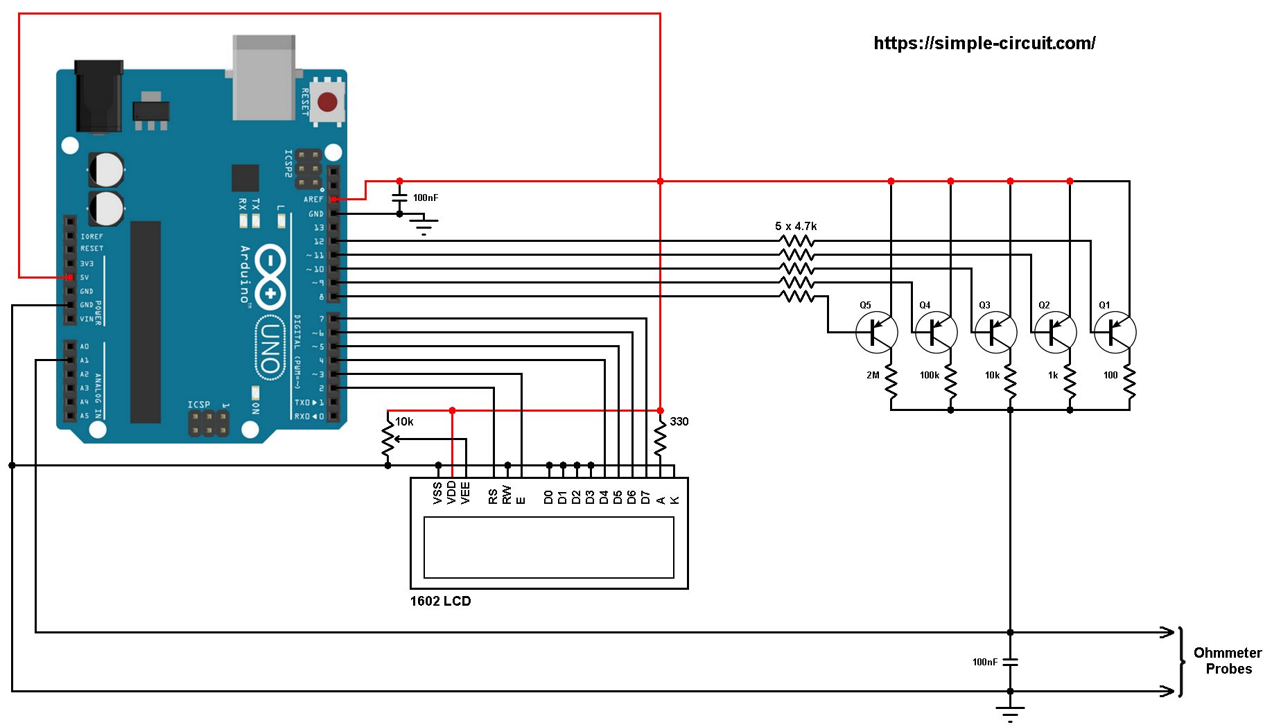
The resistor which we want to measure is connected between Arduino analog channel 1 (A1) and GND as shown in the above circuit diagram (Ohmmeter Probes). The 100nF capacitor is used to stabilize the voltage across the unknown resistor.
The five PNP transistors Q1 ~ Q5 are general purpose transistors and they are of the same type 2SA1015, 2N3906 or equivalent. They are used as electronic switches for our autoranging ohmmeter.
The emitter terminal of the five transistors are connected together to 5V pin of the Arduino board.
The collector of each transistor is connected to a different resistor. At any time there is only one ON transistor whereas the others are OFF. For better accuracy, each of the 5 resistors should have tolerance of 1% or lower.
Also, each transistor base is connected to Arduino digital pin through 4.7k ohm resistor.
The AREF pin of the Arduino board should be connected to 5V pin with 100nF capacitor between it and GND pin.
The 1602 LCD screen (2 rows and 16 columns) is used to display temperature values in degrees Celsius and degrees Fahrenheit where:
RS —> Arduino digital pin 2
E —> Arduino digital pin 3
D4 —> Arduino digital pin 4
D5 —> Arduino digital pin 5
D6 —> Arduino digital pin 6
D7 —> Arduino digital pin 7
VSS, RW, D0, D1, D2, D3 and K are connected to Arduino GND,
VEE to the 10k ohm variable resistor (or potentiometer) output,
VDD to Arduino 5V and A to Arduino 5V through 330 ohm resistor.
VEE pin is used to control the contrast of the LCD. A (anode) and K (cathode) are the back light LED pins.
Arduino autoranging ohmmeter code:
The 5 transistor bases are connected to Arduino pins 8 ~ 12, they are defined in the Arduino code as CH0 ~ CH4:
1 2 3 4 5 | #define CH0 12 #define CH1 11 #define CH2 10 #define CH3 9 #define CH4 8 |
The 5 resistors (100, 1k, 10k, 100k and 2M) are used in table (array) of 5 elements as shown below:
1 | const uint32_t res_table[5] = {100, 1000, 10000, 100000, 2000000}; |
The Arduino reads analog voltage through the unknown resistor (analog channel 1) using the following command, the corresponding digital value of this voltage is saved to variable volt_image:
1 | uint16_t volt_image = analogRead(A1) + 1; |
After measuring the voltage across the unknown resistor (digital value between 0 and 1023) we can easily calculate its resistance using the following equation:
1 | float value = (float)volt_image*res/(1023 - volt_image); |
where value is the resistance of the unknown resistor in Ohm,
volt_image is the voltage across the unknown resistor,
res is the known resistor value which may be one of the following: 100, 1000, 10000, 100000, or 2000000.
1023 is the digital value of the supply voltage (let’s say 5V).
Full Arduino code:
1 2 3 4 5 6 7 8 9 10 11 12 13 14 15 16 17 18 19 20 21 22 23 24 25 26 27 28 29 30 31 32 33 34 35 36 37 38 39 40 41 42 43 44 45 46 47 48 49 50 51 52 53 54 55 56 57 58 59 60 61 62 63 64 65 66 67 68 69 70 71 72 73 74 75 76 77 78 79 80 81 82 83 84 85 86 87 88 89 90 91 92 93 94 95 96 97 98 99 100 101 102 103 104 105 106 107 108 109 110 111 112 113 114 115 116 117 118 119 120 121 122 123 124 125 126 127 128 | /*********************************************************************** * * Arduino autoranging ohmmeter with 16x2 LCD. * This is a free software with NO WARRANTY. * http://simple-circuit.com/ * ***********************************************************************/ #include <LiquidCrystal.h> // include Arduino LCD library // LCD module connections (RS, E, D4, D5, D6, D7) LiquidCrystal lcd(2, 3, 4, 5, 6, 7); #define CH0 12 #define CH1 11 #define CH2 10 #define CH3 9 #define CH4 8 // variables byte ch_number; uint32_t res; const uint32_t res_table[5] = {100, 1000, 10000, 100000, 2000000}; char _buffer[11]; void setup(void) { Serial.begin(9600); lcd.begin(16, 2); // set up the LCD's number of columns and rows lcd.setCursor(0, 0); // move cursor to column 0, row 0 [position (0, 0)] lcd.print("Resistance ="); pinMode(CH0, OUTPUT); pinMode(CH1, OUTPUT); pinMode(CH2, OUTPUT); pinMode(CH3, OUTPUT); pinMode(CH4, OUTPUT); ch_number = 4; ch_select(ch_number); } // main loop void loop() { uint16_t volt_image = analogRead(A1) + 1; if(volt_image >= 550 && ch_number < 4) { ch_number++; ch_select(ch_number); delay(50); return; } if(volt_image <= 90 && ch_number > 0) { ch_number--; ch_select(ch_number); delay(50); return; } if(volt_image < 900) { float value = (float)volt_image*res/(1023 - volt_image); if(value < 1000.0) sprintf(_buffer, "%03u.%1u Ohm ", (uint16_t)value, (uint16_t)(value*10)%10); else if(value < 10000.0) sprintf(_buffer, "%1u.%03u kOhm", (uint16_t)(value/1000), (uint16_t)value%1000); else if(value < 100000.0) sprintf(_buffer, "%02u.%02u kOhm", (uint16_t)(value/1000), (uint16_t)(value/10)%100); else if(value < 1000000.0) sprintf(_buffer, "%03u.%1u kOhm", (uint16_t)(value/1000), (uint16_t)(value/100)%10); else sprintf(_buffer, "%1u.%03u MOhm", (uint16_t)(value/1000000), (uint16_t)(value/1000)%1000); } else sprintf(_buffer, "Over Load "); lcd.setCursor(0, 1); // move cursor to position (0, 1) lcd.print(_buffer); Serial.println(_buffer); Serial.println(); delay(500); // wait some time } void ch_select(byte n) { switch(n) { case 0: digitalWrite(CH0, LOW); digitalWrite(CH1, HIGH); digitalWrite(CH2, HIGH); digitalWrite(CH3, HIGH); digitalWrite(CH4, HIGH); break; case 1: digitalWrite(CH0, HIGH); digitalWrite(CH1, LOW); digitalWrite(CH2, HIGH); digitalWrite(CH3, HIGH); digitalWrite(CH4, HIGH); break; case 2: digitalWrite(CH0, HIGH); digitalWrite(CH1, HIGH); digitalWrite(CH2, LOW); digitalWrite(CH3, HIGH); digitalWrite(CH4, HIGH); break; case 3: digitalWrite(CH0, HIGH); digitalWrite(CH1, HIGH); digitalWrite(CH2, HIGH); digitalWrite(CH3, LOW); digitalWrite(CH4, HIGH); break; case 4: digitalWrite(CH0, HIGH); digitalWrite(CH1, HIGH); digitalWrite(CH2, HIGH); digitalWrite(CH3, HIGH); digitalWrite(CH4, LOW); } res = res_table[n]; } // end of code. |
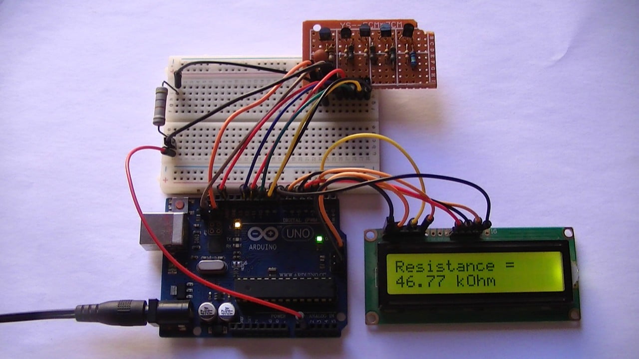
The following video shows my simple hardware circuit test:


Hi, I hope someone can help me. I completed this project and really like the format of it. However there is some holes where the readings are not accurate. The readings are reading way high. A 150K would be 198K and a 180k was 230K.
As I was going through my resistors, I found that it will not read my 120K,- 300K resistors accurately. I stopped there and did not go on. I compared values to my multimeter and another Arduino auto ranging ohm meter I built.
Very disappointing. Anybody have the same problem? Perhaps something I am doing wrong?
hank you,
Doug
Try my version Doug.
https://www.hackster.io/costalegre/auto-ranging-ohmmeter-6fa4af
I see there is some controversy above, is the current code okay to use?
Did a prototype on the breadboard & it doesn’t work correctly as CH4 stays LOW all the time & never get activated. So look like there is a coding problem. LCD Display & the serial information are fine but not showing the real value.
Is it true that more resistors – leaving smaller ‘steps’ – will yield more accurate results?
hi there please can you assist me with a problem I picked up in the above code? Line 69 reads invalid operands of types “float” and “int” to binary operators. I have checked and double cheked for typos. I really would like to make this meter
HI, this is karthik,
if(volt_image >= 550 && ch_number < 4) {
ch_number++;
ch_select(ch_number);
delay(50);
return;
}
if(volt_image 0) {
ch_number–;
ch_select(ch_number);
delay(50);
return;
}
Can you explain me the above steps in your code and its purpose.
Hello, i see you connect VCC to AREF to follow VCC fluctuations into calculations.
But, you don’t use analogReference() , or in the documentation, it’s said that when you want an exterior voltage reference with AREF, you must use analogReference(EXTERNAL).
Doc :”If you’re using an external reference on the AREF pin, you must set the analog reference to EXTERNAL before calling analogRead(). Otherwise, you will short together the active reference voltage (internally generated) and the AREF pin, possibly damaging the microcontroller on your Arduino board.
Alternatively, you can connect the external reference voltage to the AREF pin through a 5K resistor, allowing you to switch between external and internal reference voltages. Note that the resistor will alter the voltage that gets used as the reference because there is an internal 32K resistor on the AREF pin. The two act as a voltage divider, so, for example, 2.5V applied through the resistor will yield 2.5 * 32 / (32 + 5) = ~2.2V at the AREF pin.”