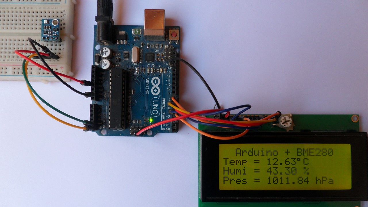
This post shows how to interface Arduino with BME280 barometric pressure, humidity and temperature sensor. Data (pressure, temperature and relative humidity values) are sent to Arduino IDE serial monitor and displayed on 20×4 LCD screen.
In this project the BME280 sensor is used in I2C mode.
The BME280 sensor from Bosch Sensortec is a low cost digital pressure, temperature and humidity sensor with good accuracy. Because pressure changes with altitude we can use it as an altimeter with ±1 meter accuracy (pressure accuracy = ±1 hPa). Some parameters of the sensor are listed below:
Pressure range: 300 … 1100 hPa (equivalent to +9000…-500m above/below sea level)
Pressure resolution: 0.01 hPa ( < 10 cm)
Temperature range: -40 … 85 °C
Temperature resolution: 0.01 °C
Humidity range: 0 … 100 %
Interface: I2C and SPI
Supply voltage range: 1.71 … 3.6 V
Hardware Required:
- Arduino board
- BME280 sensor module with 3.3V regulator and level shifter —-> BME280 datasheet
- 20×4 LCD screen
- 10k ohm variable resistor or potentiometer
- 330 ohm resistor
- Breadboard
- Jumper wires
The BME280 chip works with maximum voltage of 3.6V (supply voltage range is from 1.71 to 3.6V) which means we’ve to use a 3V3 voltage regulator to supply it from a 5V source.
Also, if we’re working with a 5V system (development board, microcontroller …) like the Arduino UNO board we’ve to use a voltage level shifter (level converter) which converts the 3.3V (comes from the BME280 chip) into 5V (goes to the Arduino) and vice versa. This level shifter is for the I2C bus lines (clock and data).
Some BME280 modules come with 3V3 voltage regulator and level shifter like the one provided by Adafruit Industries which is shown below.
A module like this can be used with 3.3V or 5V system without any problem.

In this example I’m going to use a Chinese BME280 module came with 3.3V regulator and level shifter, this mans connection will be more easier!
Interfacing Arduino with BME280 sensor circuit:
Project circuit diagram is shown below.

Note that the BME280 module shown in the circuit diagram has a 3.3V regulator and level shifter.
Generally, the BME280 module has at least 4 pins because it can work in SPI mode or I2C mode. For the I2C mode we need 4 pins: VCC, GND, SDA and SCL where:
GND (ground) is connected to Arduino GND pin
VCC is the supply pin which is connected to Arduino 5V pin
SDA is I2C bus serial data line, connected to Arduino analog pin 4 (A4)
SCL is I2C bus serial clock line, connected to Arduino analog pin 5 (A5)
The 20×4 LCD screen is used to display temperature, humidity and pressure values where:
RS —> Arduino digital pin 2
E —> Arduino digital pin 3
D4 —> Arduino digital pin 4
D5 —> Arduino digital pin 5
D6 —> Arduino digital pin 6
D7 —> Arduino digital pin 7
VSS, RW, D0, D1, D2, D3 and K are connected to Arduino GND (ground)
VEE to the variable resistor (or potentiometer) output
VDD to Arduino 5V and A to Arduino 5V through 330 ohm resistor
VEE pin is used to control the contrast of the LCD. A (anode) and K (cathode) are the back light LED pins.
Interfacing Arduino with BME280 sensor code:
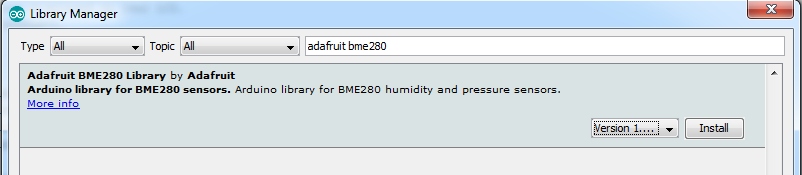
To simplify the code of this project I used a library for the BME280 sensor provided by Adafruit Industries. This library can be installed from Arduino IDE library manager (Arduino IDE —> Sketch —> Include Library —> Manage Libraries…). In the dialog box write adafruit bme280 and install the library as shown in the image below:
or it can be downloaded and installed manually, download link is below:
Adafruit BME280 Library —- direct link
You may need to install the Adafruit Unified Sensor library if it’s not already installed, download link is below:
Adafruit Unified Sensor library —- direct link
As any other I2C device, the BME280 sensor has an I2C slave address which is 0x76 or 0x77. This address depends on the connection of the SDO pin (used for SPI mode as serial data out or MISO), if the SDO pin is connected (directly or through resistor) to VCC (3.3V) the address will be 0x77, and if it’s connected to GND the address will be 0x76.
The default I2C address of the library is defined as 0x77 and my device I2C address is 0x76.
In the code the definition of the I2C slave address is as shown below:
1 2 | // define device I2C address: 0x76 or 0x77 (0x77 is library default address) #define BME280_I2C_ADDRESS 0x76 |
The initialization of the BME280 sensor is done using the function begin() which return 1 if OK and 0 if error. In the code the initialization with the previously defined address is as shown below:
1 | bme280.begin(BME280_I2C_ADDRESS) |
Reading the values of temperature, humidity, pressure and altitude is done as shown below:
1 2 3 4 5 | // get temperature, pressure and altitude from library float temperature = bme280.readTemperature(); // get temperature float humidity = bme280.readHumidity(); // get humidity float pressure = bme280.readPressure(); // get pressure float altitude_ = bme280.readAltitude(1013.25); // get altitude (this should be adjusted to your local forecast) |
Since we know the pressure, we can calculate the altitude but we’ve to know the pressure of the sea level of our location. In the code I put 1013.25 hPa. Here the idea is just to know the height of a point with respect to another one!
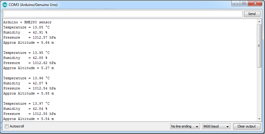
Temperature, humidity and pressure values are displayed on 20×4 LCD screen and they are sent with an approximating altitude to Arduino IDE serial monitor.
Note that 1 bar = 10000 Pa = 100 hPa. ( 1 hPa = 100 Pa = 1 millibar)
Pa: Pascal
hPa: hectoPascal
Full Arduino Code:
1 2 3 4 5 6 7 8 9 10 11 12 13 14 15 16 17 18 19 20 21 22 23 24 25 26 27 28 29 30 31 32 33 34 35 36 37 38 39 40 41 42 43 44 45 46 47 48 49 50 51 52 53 54 55 56 57 58 59 60 61 62 63 64 65 66 67 68 69 70 71 72 73 74 75 76 77 78 79 80 81 82 83 84 85 86 87 88 89 90 91 92 93 | /* * Interfacing Arduino with BME280 temperature, humidity and pressure sensor. * Temperature, humidity and pressure values are displayed on 20x4 LCD. * This is a free software with NO WARRANTY. * http://simple-circuit.com/ */ #include <Wire.h> // include Wire library, required for I2C devices #include <Adafruit_Sensor.h> // include Adafruit sensor library #include <Adafruit_BME280.h> // include adafruit library for BME280 sensor #include <LiquidCrystal.h> // include LCD library // define device I2C address: 0x76 or 0x77 (0x77 is library default address) #define BME280_I2C_ADDRESS 0x76 Adafruit_BME280 bme280; // LCD module connections (RS, E, D4, D5, D6, D7) LiquidCrystal lcd(2, 3, 4, 5, 6, 7); void setup() { Serial.begin(9600); // set up the LCD's number of columns and rows lcd.begin(20, 4); Serial.println(F("Arduino + BME280 sensor")); if (!bme280.begin(BME280_I2C_ADDRESS)) { Serial.println("Could not find a valid BME280 sensor, check wiring!"); while (1); } lcd.setCursor(2, 0); lcd.print("Arduino + BME280"); lcd.setCursor(0, 1); lcd.print("Temp ="); lcd.setCursor(0, 2); lcd.print("Humi ="); lcd.setCursor(0, 3); lcd.print("Pres ="); } char text[13]; // main loop void loop() { // get temperature, pressure and altitude from library float temperature = bme280.readTemperature(); // get temperature float humidity = bme280.readHumidity(); // get humidity float pressure = bme280.readPressure(); // get pressure float altitude_ = bme280.readAltitude(1013.25); // get altitude (this should be adjusted to your local forecast) // print data on the LCD screen // 1: print temperature sprintf(text, "%d.%02u%cC ", (int)temperature, (int)(temperature * 100)%100, 223); lcd.setCursor(7, 1); lcd.print(text); // 2: print humidity sprintf(text, "%d.%02u %% ", (int)humidity, (int)(humidity * 100)%100); lcd.setCursor(7, 2); lcd.print(text); // 3: print pressure sprintf(text, "%u.%02u hPa ", (int)(pressure / 100), (int)((uint32_t)pressure % 100)); lcd.setCursor(7, 3); lcd.print(text); // print data on the serial monitor software // 1: print temperature Serial.print("Temperature = "); Serial.print(temperature); Serial.println(" °C"); // 1: print humidity Serial.print("Humidity = "); Serial.print(humidity); Serial.println(" %"); // 3: print pressure Serial.print("Pressure = "); Serial.print(pressure / 100); Serial.println(" hPa"); // 4: print altitude Serial.print("Approx Altitude = "); Serial.print(altitude_); Serial.println(" m"); Serial.println(); // start a new line delay(2000); // wait 2 seconds } // end of code. |
Serial monitor result is shown below:
Related project:
Interfacing Arduino with BMP280 pressure and temperature sensor


is it simple to get it to disp[lay F temp instead of C?