This post shows how to interface Arduino UNO board with BMP280 barometric pressure and temperature sensor from Bosch Sensortec where values of the temperature and pressure are displayed on NOKIA 5110 (NOKIA 3310) LCD screen.
In this project the BMP280 sensor is used in I2C mode.
To see how to interface Arduino with Nokia 5110 LCD, visit the following post:
Interfacing Arduino with Nokia 5110 LCD
And to see how to interface Arduino with BMP280 sensor for the first time, take a look at this post:
Interfacing Arduino with BMP280 pressure and temperature sensor
Hardware Required:
- Arduino board
- Nokia 5110 LCD screen
- BMP280 sensor module with 3.3V regulator and level shifter —-> BMP280 datasheet
- 5 x 3.3k ohm resistor
- 5 x 2.2k ohm resistor
- Breadboard
- Jumper wires

The BMP280 chip works with maximum voltage of 3.6V (supply voltage range is from 1.71 to 3.6V) which means we’ve to use a 3V3 voltage regulator to supply it from a 5V source.
Also if we’re working with a 5V system (development board, microcontroller …) like the Arduino UNO board we’ve to use a voltage level shifter (level converter) which converts the 3.3V (comes from the BMP280 chip) into 5V (goes to the Arduino) and vice versa. This level shifter is for the I2C bus lines (clock and data).
In this example I’m using a Chinese BMP280 module came with 3.3V regulator and level shifter, this mans connection will be more easier!
Arduino with NOKIA 5110 LCD and BMP280 sensor circuit:
The following image shows project circuit schematic diagram.
Note that the BMP280 module shown in the circuit diagram has a 3.3V regulator and level shifter.
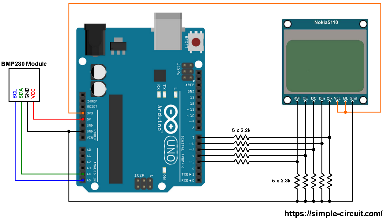
Generally, the BMP280 module has at least 4 pins because it can work in SPI mode or I2C mode. For the I2C mode we need 4 pins: VCC, GND, SDA and SCL where:
GND (ground) is connected to Arduino GND pin
VCC is the supply pin which is connected to Arduino 5V pin
SDA is I2C bus serial data line, connected to Arduino analog pin 4 (A4)
SCL is I2C bus serial clock line, connected to Arduino analog pin 5 (A5).
Nokia 5110 LCD pins are connected to Arduino UNO board as follows (each one through voltage divider):
RST (reset) pin is connected to Arduino digital pin 3
CE (chip enable) pin is connected to Arduino digital pin 4
DC (data/command) pin is connected to Arduino digital pin 5
DIN (data in) pin is connected to Arduino digital pin 6
CLK (clock) pin is connected to Arduino digital pin 7
VCC and BL are connected to Arduino 3V3 pin
GND is connected to Arduino GND pin.
Arduino with NOKIA 5110 LCD and BMP280 sensor code:
The following Arduino code requires 3 libraries from Adafruit Industries:
The first library is a driver for the Nokia 5110 LCD (PCD8544 controller) which can be installed from Arduino IDE library manager (Sketch —> Include Library —> Manage Libraries …, in the search box write “nokia” and install the one from Adafruit).
The second library is Adafruit graphics library which can be installed also from Arduino IDE library manager.
The third library is for the BMP280 sensor.
The previous 3 libraries can also be installed manually, download links are below:
Adafruit Nokia 5110 LCD library —-> direct link
Adafruit graphics library —-> direct link
Adafruit BMP280 Library —-> direct link
You may need to install the Adafruit Unified Sensor library if it’s not already installed, download link is below:
Adafruit Unified Sensor library —-> direct link
After the download, go to Arduino IDE —> Sketch —> Include Library —> Add .ZIP Library … and browse for the .zip file (previously downloaded).
The same thing for the other library files.
In the code there are total of 4 libraries, they’re included in the code as follows:
1 2 3 4 | #include <SPI.h> // include SPI library #include <Adafruit_GFX.h> // include adafruit graphics library #include <Adafruit_PCD8544.h> // include adafruit PCD8544 (Nokia 5110) library #include <Adafruit_BMP280.h> // include adafruit library for BMP280 sensor |
Nokia 5110 LCD connection with the Arduino is configured as shown below:
1 2 | // Nokia 5110 LCD module connections (CLK, DIN, D/C, CS, RST) Adafruit_PCD8544 display = Adafruit_PCD8544(7, 6, 5, 4, 3); |
As any other I2C device, the BMP280 sensor has an I2C slave address which is 0x76 or 0x77. This address depends on the connection of the SDO pin (used for SPI mode as serial data out or MISO), if the SDO pin is connected (directly or through resistor) to VCC (3.3V) the address will be 0x77, and if it’s connected to GND the address will be 0x76.
The default I2C address of the library is defined as 0x77 and my device I2C address is 0x76.
In the code, the definition of the I2C slave address is as shown below:
1 2 | // define device I2C address: 0x76 or 0x77 (0x77 is library default address) #define BMP280_I2C_ADDRESS 0x76 |
The initialization of the BMP280 sensor is done using the function begin() which returns 1 if OK and 0 if error. In the code the initialization with the previously defined address is as shown below:
1 | bmp280.begin(BMP280_I2C_ADDRESS) |
Reading the values of temperature and pressure is done as shown below:
1 2 3 | // get temperature, pressure and altitude from library float temp = bmp280.readTemperature(); // get temperature float pressure = bmp280.readPressure() / 100; // get pressure |
Note that the BMP280 sensor library returns the value of the pressure in Pa unit and to convert it to hPa we’ve to divide it by 100.
1 bar = 10000 Pa = 100 hPa. ( 1 hPa = 100 Pa = 1 millibar)
Pa: Pascal
hPa: hectoPascal
Full Arduino Code:
1 2 3 4 5 6 7 8 9 10 11 12 13 14 15 16 17 18 19 20 21 22 23 24 25 26 27 28 29 30 31 32 33 34 35 36 37 38 39 40 41 42 43 44 45 46 47 48 49 50 51 52 53 54 55 56 57 58 59 60 61 62 63 64 65 66 67 68 69 70 71 72 73 74 75 76 77 78 79 80 81 82 83 84 85 | /* * Interfacing Arduino with BMP280 sensor and Nokia 5110 LCD. * BMP280 is a pressure and temperature sensor. * This is a free software with NO WARRANTY. * http://simple-circuit.com/ */ #include <SPI.h> // include SPI library #include <Adafruit_GFX.h> // include adafruit graphics library #include <Adafruit_PCD8544.h> // include adafruit PCD8544 (Nokia 5110) library #include <Adafruit_BMP280.h> // include adafruit library for BMP280 sensor // Nokia 5110 LCD module connections (CLK, DIN, D/C, CS, RST) Adafruit_PCD8544 display = Adafruit_PCD8544(7, 6, 5, 4, 3); // define device I2C address: 0x76 or 0x77 (0x77 is library default address) #define BMP280_I2C_ADDRESS 0x76 Adafruit_BMP280 bmp280; void setup() { // initialize the display display.clearDisplay(); // clear the screen and buffer display.begin(); // you can change the contrast around to adapt the display // for the best viewing! display.setContrast(50); display.setTextSize(1); display.setTextColor(BLACK, WHITE); display.setCursor(3, 0); display.print("BMP280 SENSOR"); display.display(); if ( !bmp280.begin(BMP280_I2C_ADDRESS) ) { // connection error! display.setCursor(0, 15); display.println("Connection"); display.print("error!"); display.display(); while (1); } display.setCursor(7, 10); display.print("TEMPERATURE:"); display.setCursor(16, 31); display.print("PRESSURE:"); display.display(); } // variable declaration char text[12]; // main loop void loop() { // get temperature and pressure from library float temp = bmp280.readTemperature(); // get temperature float pressure = bmp280.readPressure() / 100; // get pressure // print data on the LCD screen // 1: print temperature display.setCursor(15, 20); if(temp >= 0) display.print(' '); else display.print('-'); sprintf(text, "%02u.%02u C", (int)abs(temp), (int)(abs(temp) * 100) % 100); display.print(text); display.drawRect(53, 20, 3, 3, BLACK); // print degree symbol ( ° ) // 2: print pressure display.setCursor(9, 41); sprintf(text, "%04u.%02u hPa", (int)pressure, (int)((uint32_t)(pressure * 100) % 100)); display.print(text); // now update the display display.display(); delay(2000); // wait 2 seconds } // end of code. |
Finally, the following video shows my hardware circuit result:


