In this blog there are some posts show how to control brushless DC motors (sensored and sensorless BLDC motors) using Arduino (project links are below). This post shows how to control a PC CD-ROM (or DVD-ROM) drive sensorless BLDC motor using Arduino UNO board and L6234 three phase motor driver. This BLDC motor is the spindle motor of the CD-ROM driver and I chose it because it doesn’t consume high power which can be easily driven by the L6234 driver.
Related Projects:
The first link contains more details about this project.
Sensorless BLDC motor control with Arduino – DIY ESC
Brushless DC motor controller using Arduino and IR2101
CD-ROM Sensored BLDC motor control with Arduino
About L6234 three phase motor driver:
The L6234 is a DMOSs triple half-bridge driver with input supply voltage up 52V and output current of
5A. It can be used in a very wide range of applications.
It has been realized in Multipower BCD60II technology which allows the combination of isolated DMOS
transistors with CMOS and Bipolar circuits on the same chip. It is available in Power DIP 20 (16+2+2)
and in Power SO 20 packages.
All the inputs are TTL/CMOS compatible and each half bridge can be driven by its own dedicated input
and enable.
The DMOS structure has an intrinsic free wheeling body diode so the use of external diodes, which are
necessary in the bipolar configuration, can be avoided. The DMOS structure allows a very low quiescent
current of 6.5 mA typ. at Vs=42V , irrespective of the load.
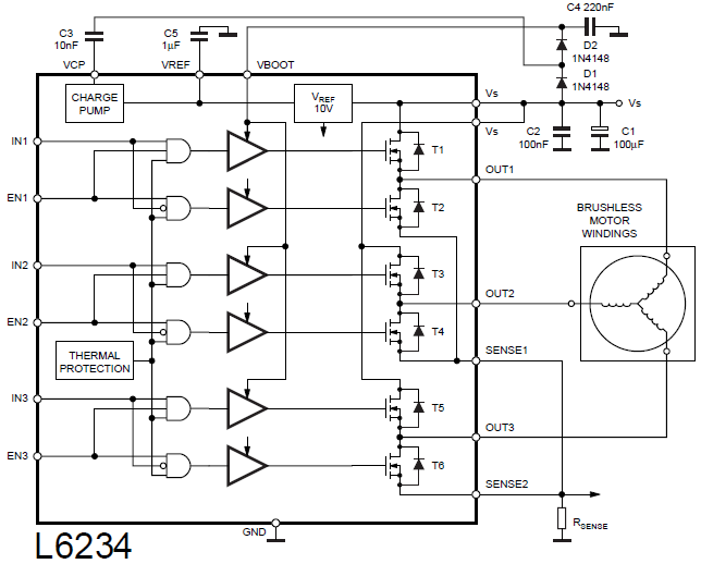
Block diagram:
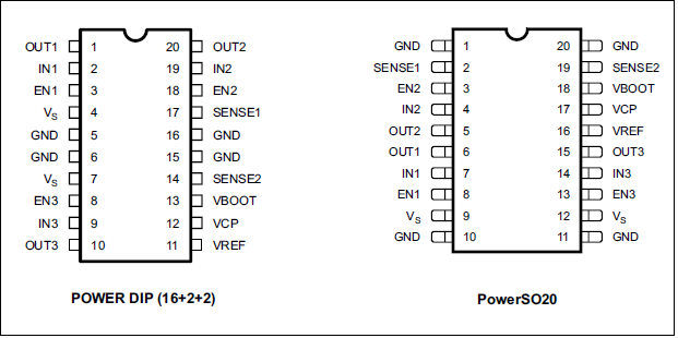
L6234 Pin configuration:
The L6234 chip is available in 20 pin PowerDIP package (16+2+2) and in PowerSO20, each package has its pin configuration as shown below:
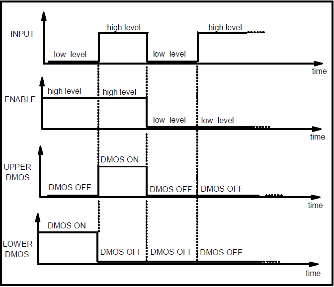
The L6234 driver has 3 outputs: OUT1, OUT2 and OUT3. Each output is controlled with 2 pins: input (IN) and enable (EN), for example OUT1 is controlled with IN1 and EN1. The figure below shows the control logic for each half-bridge:
Hardware required:
- Arduino board (UNO, NANO …)
- CD-ROM brushless dc motor
- L6234 three phase motor driver — datasheet
- 6 x 33k ohm resistor
- 3 x 10k ohm resistor
- 4 x 1 ohm resistor (with 2 W or higher)
- 2 x 1N4148 diode
- 100 uF electrolytic capacitor (with 16V or higher)
- 1 uF electrolytic capacitor (with 16V or higher)
- 220 nF (0.22 uF) ceramic capacitor
- 100 nF (0.1 uF) ceramic capacitor
- 10 nF (0.01 uF) ceramic capacitor
- 2 x push-button
- 12V source
- Breadboard
- Jumper wires
Brushless DC motor control with Arduino and L6234 circuit:
Project circuit diagram is shown below.
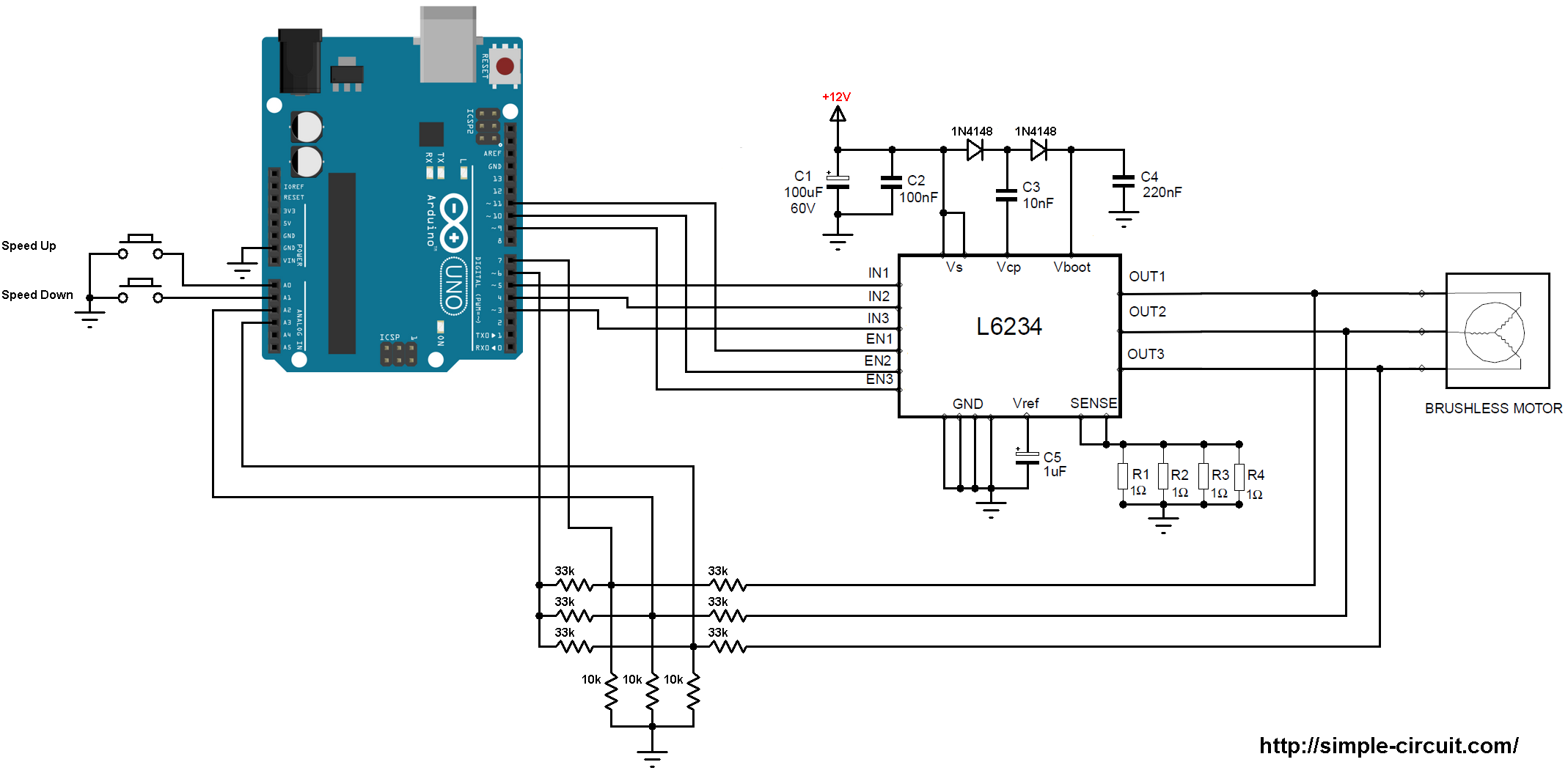
(All grounded terminals are connected together)
The speed of the brushless motor is controlled with two push buttons connected to Arduino A0 and A1 pins.
Arduino Code:
Project code is below, for more information about the code see the first related project above.
1 2 3 4 5 6 7 8 9 10 11 12 13 14 15 16 17 18 19 20 21 22 23 24 25 26 27 28 29 30 31 32 33 34 35 36 37 38 39 40 41 42 43 44 45 46 47 48 49 50 51 52 53 54 55 56 57 58 59 60 61 62 63 64 65 66 67 68 69 70 71 72 73 74 75 76 77 78 79 80 81 82 83 84 85 86 87 88 89 90 91 92 93 94 95 96 97 98 99 100 101 102 103 104 105 106 107 108 109 110 111 112 113 114 115 116 117 118 119 120 121 122 123 124 125 126 127 128 129 130 131 132 133 134 135 | /* * Sensorless brushless DC (BLDC) motor control with Arduino UNO and L6234 driver. * This is a free software with NO WARRANTY. * http://simple-circuit.com/ */ #define SPEED_UP A0 #define SPEED_DOWN A1 #define PWM_MAX_DUTY 255 #define PWM_MIN_DUTY 50 #define PWM_START_DUTY 100 byte bldc_step = 0, motor_speed; unsigned int i; void setup() { DDRD |= 0x38; // Configure pins 3, 4 and 5 as outputs PORTD = 0x00; DDRB |= 0x0E; // Configure pins 9, 10 and 11 as outputs PORTB = 0x31; // Timer1 module setting: set clock source to clkI/O / 1 (no prescaling) TCCR1A = 0; TCCR1B = 0x01; // Timer2 module setting: set clock source to clkI/O / 1 (no prescaling) TCCR2A = 0; TCCR2B = 0x01; // Analog comparator setting ACSR = 0x10; // Disable and clear (flag bit) analog comparator interrupt pinMode(SPEED_UP, INPUT_PULLUP); pinMode(SPEED_DOWN, INPUT_PULLUP); } // Analog comparator ISR ISR (ANALOG_COMP_vect) { // BEMF debounce for(i = 0; i < 10; i++) { if(bldc_step & 1){ if(!(ACSR & 0x20)) i -= 1; } else { if((ACSR & 0x20)) i -= 1; } } bldc_move(); bldc_step++; bldc_step %= 6; } void bldc_move(){ // BLDC motor commutation function switch(bldc_step){ case 0: AH_BL(); BEMF_C_RISING(); break; case 1: AH_CL(); BEMF_B_FALLING(); break; case 2: BH_CL(); BEMF_A_RISING(); break; case 3: BH_AL(); BEMF_C_FALLING(); break; case 4: CH_AL(); BEMF_B_RISING(); break; case 5: CH_BL(); BEMF_A_FALLING(); break; } } void loop() { SET_PWM_DUTY(PWM_START_DUTY); // Setup starting PWM with duty cycle = PWM_START_DUTY i = 5000; // Motor start while(i > 100) { delayMicroseconds(i); bldc_move(); bldc_step++; bldc_step %= 6; i = i - 20; } motor_speed = PWM_START_DUTY; ACSR |= 0x08; // Enable analog comparator interrupt while(1) { while(!(digitalRead(SPEED_UP)) && motor_speed < PWM_MAX_DUTY){ motor_speed++; SET_PWM_DUTY(motor_speed); delay(100); } while(!(digitalRead(SPEED_DOWN)) && motor_speed > PWM_MIN_DUTY){ motor_speed--; SET_PWM_DUTY(motor_speed); delay(100); } } } void BEMF_A_RISING(){ ADCSRB = (0 << ACME); // Select AIN1 as comparator negative input ACSR |= 0x03; // Set interrupt on rising edge } void BEMF_A_FALLING(){ ADCSRB = (0 << ACME); // Select AIN1 as comparator negative input ACSR &= ~0x01; // Set interrupt on falling edge } void BEMF_B_RISING(){ ADCSRA = (0 << ADEN); // Disable the ADC module ADCSRB = (1 << ACME); ADMUX = 2; // Select analog channel 2 as comparator negative input ACSR |= 0x03; } void BEMF_B_FALLING(){ ADCSRA = (0 << ADEN); // Disable the ADC module ADCSRB = (1 << ACME); ADMUX = 2; // Select analog channel 2 as comparator negative input ACSR &= ~0x01; } void BEMF_C_RISING(){ ADCSRA = (0 << ADEN); // Disable the ADC module ADCSRB = (1 << ACME); ADMUX = 3; // Select analog channel 3 as comparator negative input ACSR |= 0x03; } void BEMF_C_FALLING(){ ADCSRA = (0 << ADEN); // Disable the ADC module ADCSRB = (1 << ACME); ADMUX = 3; // Select analog channel 3 as comparator negative input ACSR &= ~0x01; } void AH_BL(){ PORTB = 0x04; PORTD &= ~0x18; PORTD |= 0x20; TCCR1A = 0; // Turn pin 11 (OC2A) PWM ON (pin 9 & pin 10 OFF) TCCR2A = 0x81; // } void AH_CL(){ PORTB = 0x02; PORTD &= ~0x18; PORTD |= 0x20; TCCR1A = 0; // Turn pin 11 (OC2A) PWM ON (pin 9 & pin 10 OFF) TCCR2A = 0x81; // } void BH_CL(){ PORTB = 0x02; PORTD &= ~0x28; PORTD |= 0x10; TCCR2A = 0; // Turn pin 10 (OC1B) PWM ON (pin 9 & pin 11 OFF) TCCR1A = 0x21; // } void BH_AL(){ PORTB = 0x08; PORTD &= ~0x28; PORTD |= 0x10; TCCR2A = 0; // Turn pin 10 (OC1B) PWM ON (pin 9 & pin 11 OFF) TCCR1A = 0x21; // } void CH_AL(){ PORTB = 0x08; PORTD &= ~0x30; PORTD |= 0x08; TCCR2A = 0; // Turn pin 9 (OC1A) PWM ON (pin 10 & pin 11 OFF) TCCR1A = 0x81; // } void CH_BL(){ PORTB = 0x04; PORTD &= ~0x30; PORTD |= 0x08; TCCR2A = 0; // Turn pin 9 (OC1A) PWM ON (pin 10 & pin 11 OFF) TCCR1A = 0x81; // } void SET_PWM_DUTY(byte duty){ if(duty < PWM_MIN_DUTY) duty = PWM_MIN_DUTY; if(duty > PWM_MAX_DUTY) duty = PWM_MAX_DUTY; OCR1A = duty; // Set pin 9 PWM duty cycle OCR1B = duty; // Set pin 10 PWM duty cycle OCR2A = duty; // Set pin 11 PWM duty cycle } |
Brushless DC motor control with Arduino and L6234 video:
The small video below shows my prototype hardware circuit result.
Reference:
L6234 datasheet


Hello,
I recently stumbled upon this blogpost about the L6234 BLDC controller. I would like to make a small breakout board using this controller for a gimbal project I’m working on (in combination with an AS5600 magnetic position sensor). I’m relatively new to circuit board design, so I’m trying to interpret you schematic but I have a few questions:
1. Is it correct to assume that the top part of the circuit (i.e., capacitors and diodes) are all meant to smoothen the DC voltage supply to the circuit and reduce noise?
2. Can you explain the purpose of the wires running from the BLDC to the little circuit at the bottom with the 33k and 10k resistors, leading to GND, A2 and A3?
Hope you can help out. Thanks for sharing this useful blog post!
Best,
Frank
In the video u were used a big capacitor.. what is the need of that capacitor and why don’t added in circuit
It’s connected between + and – of the 12V power supply, it is used to provide more sufficient and smooth DC voltage to the circuit. You may use one with 16V 470uF.
Really this circuit and program will work .. please say yes or no? Because I want to try this circuit. I expect ur kind reply…
Hi! Which source did you use to supply the BLDC motor.
Looking forward to receiving your response as soon as possible.
12V 5A source will be fine!
Is it possible to use the type of Lipo battery that is used for the drone.
Please I need this circuit with upto 20A/30A/40A please how to increase the current? I want to use it for my home made quadcopter
Code does not compile 🙁 Can you fix please? Thanks!
I am trying to run a quadcopter motor using some sort of driver like above mentioned L6234 ,but I think it’s underrated for that purpose ,can someone suggest me which driver (MOSFET integrated) I can use to run a quadcopter sensorless BLDC rc motor smoothly ?
motor_speed’ not name a type cpode error
for(i = 0; i 100) {