A month ago, I build a sensorless brushless DC motor controller using Arduino UNO board, IR2104 gate driver, mosfets …. and now in this post I’m going to build exactly the same controller but using IR2101 instead of the IR2104. Previous project link is the one below (contains more details about sensorless BLDC motor and back-emf):
Sensorless BLDC motor control with Arduino – DIY ESC
Components Required:
- Arduino UNO board —> datasheet
- Brushless DC (BLDC) motor
- 6 x 06N03LA N-type mosfet (or equivalent) – datasheet
- 3 x IR2101 (IR2101S) gate driver IC – datasheet
- 6 x 33k ohm resistor
- 3 x 10k ohm resistor
- 6 x 10 ohm resistor
- 3 x IN4148 diode
- 3 x 10uF capacitor
- 3 x 2.2uF capacitor
- 2 x pushbutton
- 12V source
- Breadboard
- Jumper wires
Sensorless brushless DC motor control with Arduino circuit:
Project circuit schematic is shown below.
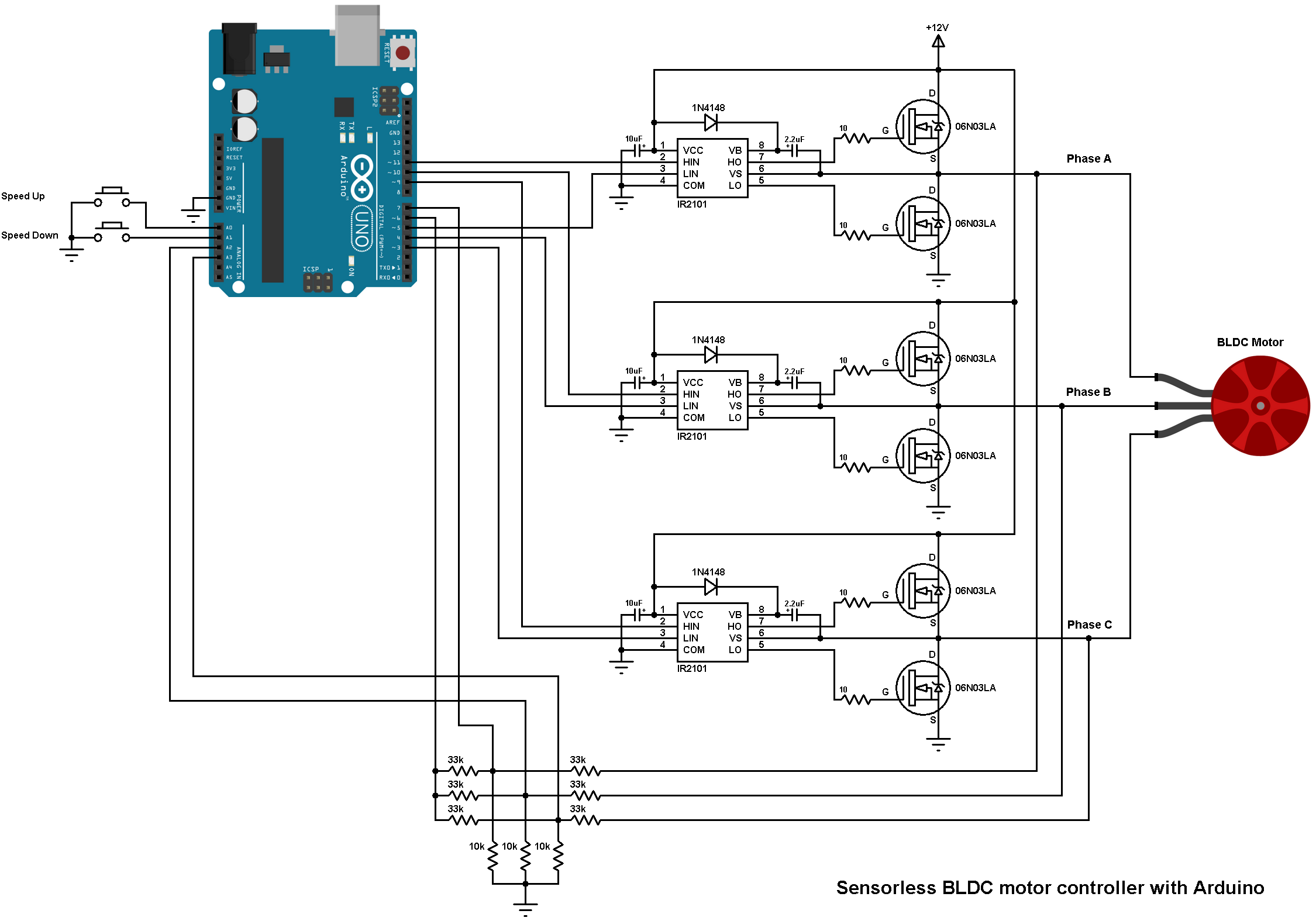
Note that all grounded terminals are connected together.
In the circuit there are 2 pushbuttons, one is used to increase BLDC motor speed and the 2nd one is used to decrease it.
The first three 33k (connected to motor phases) and the three 10k resistors are used as voltage dividers, because we can not supply the microcontroller with 12V, the other three 33k resistors generate the virtual natural point. The virtual natural point is connected to Arduino pin 6.
The Arduino UNO board is based on the ATmega328P microcontroller which has one analog comparator. The positive input of this comparator is on Arduino uno pin 6 (AIN0) and the negative input can be pin 7 (AIN1), A0 (ADC0), A1 (ADC1), A2 (ADC2), A3 (ADC3), A4 (ADC4) or A5 (ADC5). So I connected the virtual natural point to the positive pin of the analog comparator (pin 6), phase A BEMF to pin 7 (AIN1), phase B BEMF to pin A2 and phase C BEMF to pin A3. Each time the comparator compares the virtual point with the BEMF of one phase (this is done in the software). This minimizes the hardware needed and simplifies the circuit.
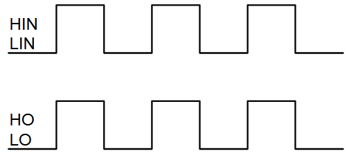
The IR2101 chips are used to control high side and low side mosfets of each phase. The switching between the high side and the low side is done according to the control lines HIN and LIN. The figure below shows input and output timing diagram:
The HIN lines of the three IR2101 are connected to pins 11, 10 and 9 respectively for phase A, phase B and phase C. The Arduino UNO can generate PWM signals on that pins where only high side mosfets are PWMed.
Sensorless BLDC motor control with Arduino code:
The code below does not use any BLDC motor library.
As mentioned above, Arduino pins 9, 10 and 11 can generate PWM signals where pin 9 and pin 10 are related with Timer1 module (OC1A and OC1B) and pin 11 is related with Timer2 module (OC2A). Both Timer modules are configured to generate a PWM signal with a frequency of about 31KHz and a resolution of 8 bits. The duty cycles of the PWM signals are updated when a pushbutton is pressed (speed up or speed down) by writing to their registers (OCR1A, OCR1B and OCR2A).
The analog comparator compares the positive input AIN0 (Arduino pin 6) with the negative input which can be AIN1 (pin 7), ADC2 (pin A2) or ADC3 (pin A3). When the positive pin voltage is higher than the negative pin voltage, the output of the analog comparator ACO is set, and when the positive pin voltage is lower than the negative pin voltage, ACO is cleared.
In this project I used the analog comparator interrupt and I used its interrupt on rising (transition from low to high) and interrupt on falling (transition from high to low), this makes the zero crossing events interrupt the microcontroller.
To fully understand the code, read the ATmega328 datasheet!
1 2 3 4 5 6 7 8 9 10 11 12 13 14 15 16 17 18 19 20 21 22 23 24 25 26 27 28 29 30 31 32 33 34 35 36 37 38 39 40 41 42 43 44 45 46 47 48 49 50 51 52 53 54 55 56 57 58 59 60 61 62 63 64 65 66 67 68 69 70 71 72 73 74 75 76 77 78 79 80 81 82 83 84 85 86 87 88 89 90 91 92 93 94 95 96 97 98 99 100 101 102 103 104 105 106 107 108 109 110 111 112 113 114 115 116 117 118 119 120 121 122 123 124 125 126 127 128 129 130 131 132 133 134 135 136 137 138 139 140 141 142 143 144 145 146 147 148 149 150 151 152 153 154 155 156 157 158 159 160 161 162 163 164 165 166 167 168 169 170 171 172 173 174 175 176 177 178 179 180 | /* Sensorless brushless DC (BLDC) motor control with Arduino UNO (Arduino DIY ESC). * This is a free software with NO WARRANTY. * http://simple-circuit.com/ */ #define SPEED_UP A0 // BLDC motor speed-up button #define SPEED_DOWN A1 // BLDC motor speed-down button #define PWM_MAX_DUTY 255 #define PWM_MIN_DUTY 50 #define PWM_START_DUTY 100 byte bldc_step = 0, motor_speed; unsigned int i; void setup() { DDRD |= 0x38; // Configure pins 3, 4 and 5 as outputs PORTD = 0x00; DDRB |= 0x0E; // Configure pins 9, 10 and 11 as outputs PORTB = 0x31; // Timer1 module setting: set clock source to clkI/O / 1 (no prescaling) TCCR1A = 0; TCCR1B = 0x01; // Timer2 module setting: set clock source to clkI/O / 1 (no prescaling) TCCR2A = 0; TCCR2B = 0x01; // Analog comparator setting ACSR = 0x10; // Disable and clear (flag bit) analog comparator interrupt pinMode(SPEED_UP, INPUT_PULLUP); pinMode(SPEED_DOWN, INPUT_PULLUP); } // Analog comparator ISR ISR (ANALOG_COMP_vect) { // BEMF debounce for(i = 0; i < 10; i++) { if(bldc_step & 1){ if(!(ACSR & 0x20)) i -= 1; } else { if((ACSR & 0x20)) i -= 1; } } bldc_move(); bldc_step++; bldc_step %= 6; } void bldc_move(){ // BLDC motor commutation function switch(bldc_step){ case 0: AH_BL(); BEMF_C_RISING(); break; case 1: AH_CL(); BEMF_B_FALLING(); break; case 2: BH_CL(); BEMF_A_RISING(); break; case 3: BH_AL(); BEMF_C_FALLING(); break; case 4: CH_AL(); BEMF_B_RISING(); break; case 5: CH_BL(); BEMF_A_FALLING(); break; } } void loop() { SET_PWM_DUTY(PWM_START_DUTY); // Setup starting PWM with duty cycle = PWM_START_DUTY i = 5000; // Motor start while(i > 100) { delayMicroseconds(i); bldc_move(); bldc_step++; bldc_step %= 6; i = i - 20; } motor_speed = PWM_START_DUTY; ACSR |= 0x08; // Enable analog comparator interrupt while(1) { while(!(digitalRead(SPEED_UP)) && motor_speed < PWM_MAX_DUTY){ motor_speed++; SET_PWM_DUTY(motor_speed); delay(100); } while(!(digitalRead(SPEED_DOWN)) && motor_speed > PWM_MIN_DUTY){ motor_speed--; SET_PWM_DUTY(motor_speed); delay(100); } } } void BEMF_A_RISING(){ ADCSRB = (0 << ACME); // Select AIN1 as comparator negative input ACSR |= 0x03; // Set interrupt on rising edge } void BEMF_A_FALLING(){ ADCSRB = (0 << ACME); // Select AIN1 as comparator negative input ACSR &= ~0x01; // Set interrupt on falling edge } void BEMF_B_RISING(){ ADCSRA = (0 << ADEN); // Disable the ADC module ADCSRB = (1 << ACME); ADMUX = 2; // Select analog channel 2 as comparator negative input ACSR |= 0x03; } void BEMF_B_FALLING(){ ADCSRA = (0 << ADEN); // Disable the ADC module ADCSRB = (1 << ACME); ADMUX = 2; // Select analog channel 2 as comparator negative input ACSR &= ~0x01; } void BEMF_C_RISING(){ ADCSRA = (0 << ADEN); // Disable the ADC module ADCSRB = (1 << ACME); ADMUX = 3; // Select analog channel 3 as comparator negative input ACSR |= 0x03; } void BEMF_C_FALLING(){ ADCSRA = (0 << ADEN); // Disable the ADC module ADCSRB = (1 << ACME); ADMUX = 3; // Select analog channel 3 as comparator negative input ACSR &= ~0x01; } void AH_BL(){ PORTD &= ~0x28; PORTD |= 0x10; TCCR1A = 0; // Turn pin 11 (OC2A) PWM ON (pin 9 & pin 10 OFF) TCCR2A = 0x81; // } void AH_CL(){ PORTD &= ~0x30; PORTD |= 0x08; TCCR1A = 0; // Turn pin 11 (OC2A) PWM ON (pin 9 & pin 10 OFF) TCCR2A = 0x81; // } void BH_CL(){ PORTD &= ~0x30; PORTD |= 0x08; TCCR2A = 0; // Turn pin 10 (OC1B) PWM ON (pin 9 & pin 11 OFF) TCCR1A = 0x21; // } void BH_AL(){ PORTD &= ~0x18; PORTD |= 0x20; TCCR2A = 0; // Turn pin 10 (OC1B) PWM ON (pin 9 & pin 11 OFF) TCCR1A = 0x21; // } void CH_AL(){ PORTD &= ~0x18; PORTD |= 0x20; TCCR2A = 0; // Turn pin 9 (OC1A) PWM ON (pin 10 & pin 11 OFF) TCCR1A = 0x81; // } void CH_BL(){ PORTD &= ~0x28; PORTD |= 0x10; TCCR2A = 0; // Turn pin 9 (OC1A) PWM ON (pin 10 & pin 11 OFF) TCCR1A = 0x81; // } void SET_PWM_DUTY(byte duty){ if(duty < PWM_MIN_DUTY) duty = PWM_MIN_DUTY; if(duty > PWM_MAX_DUTY) duty = PWM_MAX_DUTY; OCR1A = duty; // Set pin 9 PWM duty cycle OCR1B = duty; // Set pin 10 PWM duty cycle OCR2A = duty; // Set pin 11 PWM duty cycle } |
The video below shows how project is working (in this video I used the IR2104S chips).


Hi, I built the project using IFRZ44N MOSFETs… My experience:
-The “startup” (open loop code patch to get the motor running) only works in about 1 in 4 power-on cycles…. Sometimes it starts the wrong direction and stops, sometimes it just locks up and buzzes, other times it starts up and spins in the CCW direction as expected.
-Regardless of the startup state, when the code hits the steady state condition, if I spin the spindle CCW by hand, the motor starts up and runs seemingly fine.
Thank you for this nice project, it works great on most bldc motors.
But I like to know if the analog comparator could be switched to hall sensors ?
Or do I need to change code for it to work?
I got some motors that give way more back-emf on higher speeds and blow my transistors. switching to hall is simpler than finding the right resistors setup with all those transisters I already killed.
Thanks
This is well described and easy to follow. I think electrical and electronics engineering can easily try this project provided they have the necessary items needed to build the project.
Please I really want to know the connection of the 12v to make the motor to run on
Hi, first of all great stuff!!
I wanted your advice on how to change the code to invert the output PWM for the low-side gate drivers. How would I go about to achieve that?
Many thanks
We did above ckt. Simulation in proteus and put the same code to it but the motor is not running at desired speed and after some time motor gets automatically reversed so what changes should make in either program or ckt. Diag.
can you please tell me the bldc motor specification which you used in this project
Thank you very much !
Thank you very much ! I built the circuit same as you mention, except the Mosfet IRFP064N is used instead. it’s not working for me 🙁
In open loop mode , motor starts spinning, at the moment when exiting from first loop and activating the ISR (comparator) , the motor stops immediately, and keep blocked.
please could you advise me , how can I resolve this issue ?
hello, is it possible to have a reverse function, and how much code change is there and can the nano handle it
Mr. Simple Project
About the use of the mosfet. Can i use an IGBT power transistor instead of that mosfet?
Thank in advance, Neil
Hello, very nice article!
One question: what should be the resistors’ power?
Is it fine 1/4w or more?
Thanks in advance, E.
If you mean BEMF resistors, any one can do the job (1/4W included) because there is a very small current (in milliamps) that passes through each one.
hello mister simple project,
at the moment,the pcb i built,based on your présentation of the pcb with the 33K and 10K resistors with IR2104 + IRF840 is now all done and finally seems to pulse frequencys,by playing with buttons – and + ,osciloscope show me a range of duty frequency from 40000 KHZ to 140 KHZ,however my 1400 kv brushless 12 vdc motor does not run..
the only stuff this motor does,is ,by approching my ear of it,i can ear the voltage noise,pretty close as the noise of a lambda inverter from the traditionnal market,but nothing more,the motor dont moove yet..how come with variables frequencys visualised on the osciloscope screen??(measurments done on the minus from the power side and each phases output)…. what went wrong? i dont think the problem could come from the pcb itself because it does pulsing apparently properly…..?
i tryed severals softwares,and your own one of course as well..
if you have some tips and helps,it would be definitly nice,hopefully you have 😉
thanks to care
regards
nico
sorry, forget to mentionned an important points:
– each sin of each phase (a,b,c),are identicals with each other,so hopefully it means “this is normal”?
does it means that the signal and all the command side and power side are well done and operationnal somewhere?
thanks mister simple projects 😉
Thank you very much. I followed shematic and used Mosfet STP75NF75 instead for my project. It works excatly. And Mosfet isn’t overheat during BLDC motor is running. Many many thanks for you. ^^!
Good, this will help others!
While using mosfet P55NF06 with IR2101 ic , Mosfet is getting overheated.
can we use the above combination of mosfet and ic.
If high side and low side mosfets (of the same bridge) are fired at the same time they will cause a short circuit which causes the 2 mosfets to get overheated.
Check all the mosfets, may be one (or more) of them is damaged, and check the connections of the circuit.
Thank you for project.
I want to control 700W, 12V, 60A(max) brushless motor. Can i use infineon BSC050N03LS G mosfet? (30V, 5mR, 80A)
Is suitable? Or Which mosfet can i use? Please help.
Thank you very much for the content.
Will this circuit operate for BLDC ceiling fan motor of 350 RPM, 12V, 2.5A. If not what need to be change. Can you please tell me sir ? Thankyou
thank you very much !
I want to use potentiometer to adjust speed of motor, can you give me the code to do this. Thanks
I don’t know if it will give you a good result because the ADC and the analog comparator of the ATmega328P microcontroller share the same multiplexer!
if you use LM339 to compare, can you do that?
Yes you can do it as what I did with PIC18F4550 microcontroller:
i watched it ,but i didn’t understand code for pic18f.. can you help me write the code for arduino please!
thanks if so it can do, we’ll wait for analog pot update for this arduino version..
I have a problem, I cant put a PWM on D10. No problem on D9 and D11. Why is this possible?
I do that with ir2101 and mosfet irf3205. Mosfets are hot, and motor not run. Can you tell me why it happend and how to repair it. Thank you
The IRF3205 is not a good choice for this project, try with a different mosfet with characteristics similar (or better) to the one used here.
That characteristics are in the datasheet (turn-on delay time, rise time, Rds(on) ….).
i try many times, and it’s running, but the current picked up 8.2 amps, it’s too high, i using motor xxd 2212 2700kv, 12volt dc, can you give me Ampe of device consumption in this video, please!
Hey, in hope of an reply, did you ever find an solution to the problem.
O how I love this new finding website.
I am busy in research and developing in green energy, but I know nothing about programming and writing source code .
Is it possible to help me change some coding in this very same project of the Sensorless BLDC motor control with Arduino code?
If possible, please confirm so I may or can inform what I need in this project and coding to serve my research and purpose in this new invention of mine in GREEN ENERGY.
Looking forward to hear from you soon.
Kind regards.
Gert van Kraayenburg
South Africa.
Hi Gert please contact me on my email as I think we hace the same intrests because I am also working on green energy projects etc.
Hi Gert, my email address is to [email protected]
Sorry’ [email protected]
I am from gauteng south africa
i use ir2103 and spp06n80 with 220v motor power supply, is it possible to use sensorless directly on arduino output instead of power?