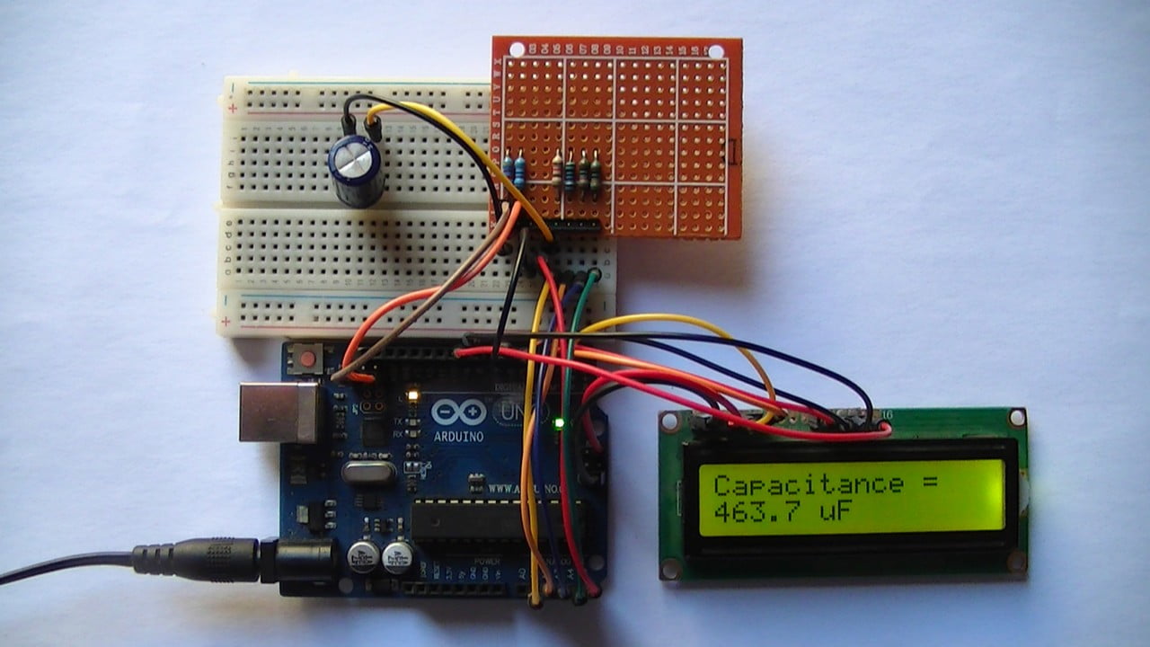
This project shows how to build a capacitance meter based on Arduino board where the value of capacitor capacitance is displayed on 16×2 LCD screen and on the laptop through serial monitor software (for example Arduino IDE serial monitor).
Working Principle:
When a capacitor is connected in series with a simple resistor (series RC circuit) and by applying a certain voltage VS, the capacitor voltage VC increases exponentially towards VS according to the following equation:
![]()
RC Called time constant (Tau) which is time when VC = 0.632VS where R is in Ω and C in Farads.
So, from the previous function, if we know VS, VC, R and t we can calculate the value of C.
The Arduino microcontroller ATmega328P (uno, Nano, Mini …) has a built-in analog comparator which will be used in this project to detect the voltage of the capacitor when it goes above VS/2 (approximately 2.5V).
When VC = 0.5VS the capacitance value C = t/[R x ln(0.5)]
Timer1 module is used to count time t between VC = 0 and VC = VS/2.
To get a voltage of VS/2 we may use voltage divider using 2 similar resistors.
Project Hardware Required:
- Arduino board
- 1602 LCD screen
- 2 x 4.7k ohm resistor
- 100k ohm resistor
- 10k ohm resistor
- 1k ohm resistor
- 220 ohm resistor
- 330 ohm resistor
- 10k ohm variable resistor or potentiometer
- Breadboard
- Jumper wires
Arduino capacitance meter circuit:
Project circuit diagram is the one below.
warning: the capacitor should be fully discharged before placing it in the circuit!
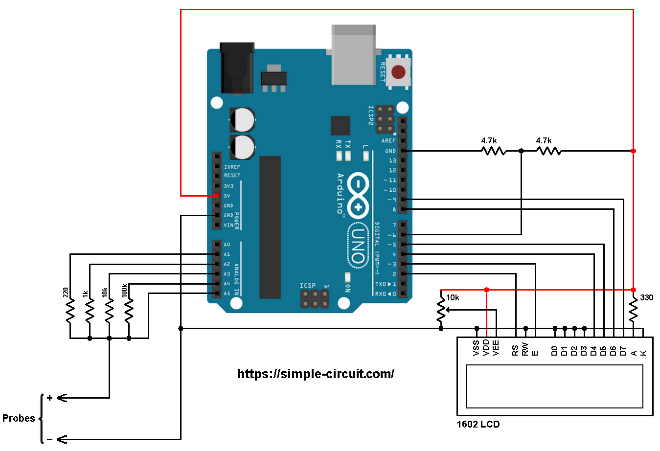
The circuit shown above is for an autoranging capacitance meter, the capacitor under test is connected to the Probes terminals + and –. The – terminal is directly connected to Arduino GND pin.
The capacitor under test is charged using one of the three resistors: 1k, 10k or 100k. The Arduino initiates the charging of the capacitor through one resistor according to its capacity. The 220 ohm resistor is used for discharging the capacitor.
With these resistors the Arduino outputs a maximum current of 5/1k = 5mA (while charging the capacitor) and sinks a maximum current of 5/220 = 22.7mA (while discharging the capacitor).
The reference voltage (approximately 2.5V) comes from the 2 x 4.7k resistors voltage divider, it’s connected to Arduino digital pin 6, this is AIN0 pin of the Atmega328P MCU which is analog comparator positive input pin.
The capacitor positive terminal is connected to Arduino analog channel 5 (A5). This pin is used as negative input of the analog comparator and also to read capacitor voltage during discharge.
The 1602 LCD screen (2 rows and 16 columns) is used to display temperature values in degrees Celsius and degrees Fahrenheit where:
RS —> Arduino digital pin 2
E —> Arduino digital pin 3
D4 —> Arduino digital pin 4
D5 —> Arduino digital pin 5
D6 —> Arduino digital pin 8
D7 —> Arduino digital pin 9
VSS, RW, D0, D1, D2, D3 and K are connected to Arduino GND,
VEE to the 10k ohm variable resistor (or potentiometer) output,
VDD to Arduino 5V and A to Arduino 5V through 330 ohm resistor.
VEE pin is used to control the contrast of the LCD. A (anode) and K (cathode) are the back light LED pins.
Arduino capacitance meter code:
Hints:
Capacitor discharge pin is Arduino analog pin 1 (A1) and it’s connected to the capacitor positive terminal through 220 ohms resistor. Capacitor charging pins are A2, A3 and A4 and they’re connected to the capacitor positive terminal respectively through 1k, 10k and 100k. All those pins are defined in the code as shown below:
1 2 3 4 | #define discharge_pin A1 #define channel0_pin A2 #define channel1_pin A3 #define channel2_pin A4 |
The 3 resistors (1k, 10k and 100k) are used in a table (array) of 3 elements as shown below:
1 | const uint32_t res_table[3] = {1000, 10000, 100000}; |
At the beginning, the Arduino starts discharging the capacitor by writing logic low to discharge_pin until the capacitor is fully discharged through the 220 ohms resistor. While the discharge_pin is low, the ADC module keeps checking capacitor voltage (channel 5).
After the capacitor is fully discharged, the ADC module is disabled and analog comparator interrupt is enabled, a charging voltage is applied to the capacitor through one series resistor (1k, 10k or 100k) and Timer1 module starts counting until the analog comparator interrupt occurs. This interrupt tells the microcontroller that the capacitor voltage is approximately equal to the reference voltage which is equal to 2.5V.
So, we can calculate capacitance value since we know the values of the supply voltage (5V), series resistance (1k, 10k or 100k) and time.
Note that Timer1 module is configured to increment by 1 every 62.5 microseconds (prescaler = 1).
Full Arduino code:
1 2 3 4 5 6 7 8 9 10 11 12 13 14 15 16 17 18 19 20 21 22 23 24 25 26 27 28 29 30 31 32 33 34 35 36 37 38 39 40 41 42 43 44 45 46 47 48 49 50 51 52 53 54 55 56 57 58 59 60 61 62 63 64 65 66 67 68 69 70 71 72 73 74 75 76 77 78 79 80 81 82 83 84 85 86 87 88 89 90 91 92 93 94 95 96 97 98 99 100 101 102 103 104 105 106 107 108 109 110 111 112 113 114 115 116 117 118 119 120 121 122 123 124 125 126 127 128 129 130 131 132 133 134 135 136 137 138 139 140 141 142 143 144 145 146 147 148 149 150 151 152 153 154 155 156 157 158 159 160 161 162 | /*********************************************************************** * * Arduino based capacitance meter. * Capacitance value is displayed on 16x2 LCD. * This is a free software with NO WARRANTY. * http://simple-circuit.com/ * ***********************************************************************/ #include <LiquidCrystal.h> // include Arduino LCD library // LCD module connections (RS, E, D4, D5, D6, D7) LiquidCrystal lcd(2, 3, 4, 5, 8, 9); #define discharge_pin A1 #define channel0_pin A2 #define channel1_pin A3 #define channel2_pin A4 // variables bool ok; byte ch_number; const uint32_t res_table[3] = {1000, 10000, 100000}; uint32_t res, t_mul; char _buffer[9]; void setup(void) { Serial.begin(9600); lcd.begin(16, 2); // set up LCD's number of columns and rows lcd.setCursor(0, 0); // move cursor to column 0, row 0 [position (0, 0)] lcd.print("Capacitance ="); pinMode(discharge_pin, OUTPUT); digitalWrite(discharge_pin, LOW); // Timer1 module configuration TCCR1A = 0; TCCR1B = 0; TIMSK1 = 1; // enable Timer1 overflow interrupt ADCSRA = 0x04; // disable ADC module ADMUX = 0x45; // select channel 5 ADCSRB = (1 << ACME); // comparator negative input comes from ADC multiplexer ACSR = 0x12; // configure analog comparator & its interrupt (interrupt on falling edge) ch_number = 2; } // analog comparator ISR ISR (ANALOG_COMP_vect) { TCCR1B = 0; // disable Timer1 // disconnect all charging pins pinMode(channel0_pin, INPUT); pinMode(channel1_pin, INPUT); pinMode(channel2_pin, INPUT); // start discharging the capacitor pinMode(discharge_pin, OUTPUT); digitalWrite(discharge_pin, LOW); ok = 1; // process completed ACSR &= ~0x08; // disable analog comparator interrupt } // Timer1 overflow ISR ISR(TIMER1_OVF_vect) { t_mul++; if(ch_number != 0) { ch_number = 0; ch_select(ch_number); } } // main loop void loop() { // reset every thing TCNT1 = 0; t_mul = 0; ok = 0; // wait for capacitor discharge ADCSRA |= 0x80; // enable ADC uint16_t volt; do { ADCSRA |= 1 << ADSC; // start conversion while(ADCSRA & 0x40) delay(1); // wait for conversion complete volt = ADCL | ADCH << 8; // read analog data } while (volt > 0); ADCSRA &= ~0x80; // disable ADC delay(100); // disconnect discharging pin pinMode(discharge_pin, INPUT); ACSR |= 0x08; // enable analog comparator interrupt TCCR1B = 1; // start Timer1 with prescaler = 1 (1 tick every 62.5 ns) ch_select(ch_number); while(ok == 0) delay(1); // wait for process complete (charging the capacitor) int32_t _time = 65536 * t_mul + TCNT1; uint32_t cap; if(ch_number == 0) cap = -62.5 * _time/(res * log(0.5)); // cap is in nF else { _time -= 385; // apply some correction if(_time < 0) _time = 0; cap = -62500.0 * _time/(res * log(0.5)); // cap is in pF } if( (ch_number == 1 && cap < 10000) || (ch_number == 0 && cap < 10) ) ch_number = 2; if( (ch_number == 2 && cap > 12000) || (ch_number == 0 && cap < 500) ) ch_number = 1; if(ch_number != 0) { if(cap < 1000) // if cap < 1000 pF = 1 nF sprintf(_buffer, "%03u pF ", (uint16_t)cap); else sprintf(_buffer, "%03u nF ", (uint16_t)(cap/1000) % 1000); } else { if(cap < 1000000) // if cap < 1000000 nF = 1000 uF sprintf(_buffer, "%03u.%1u uF", (uint16_t)(cap/1000), (uint16_t)(cap/100)%10); else sprintf(_buffer, "%u uF ", (uint16_t)(cap/1000)); } lcd.setCursor(0, 1); // move cursor to position (0, 1) lcd.print(_buffer); Serial.print("Capacitance = "); Serial.println(_buffer); Serial.println(); delay(1000); // wait a second } void ch_select(byte n) { switch(n) { case 0: pinMode(channel1_pin, INPUT); pinMode(channel2_pin, INPUT); pinMode(channel0_pin, OUTPUT); digitalWrite(channel0_pin, HIGH); break; case 1: pinMode(channel0_pin, INPUT); pinMode(channel2_pin, INPUT); pinMode(channel1_pin, OUTPUT); digitalWrite(channel1_pin, HIGH); break; case 2: pinMode(channel0_pin, INPUT); pinMode(channel1_pin, INPUT); pinMode(channel2_pin, OUTPUT); digitalWrite(channel2_pin, HIGH); } res = res_table[n]; } // end of code. |
The video below shows my protoboard circuit tests with some different capacitors:
Related Project:
Arduino Based Auto-Ranging Ohmmeter


Thanks
Thank you for this tutorial. I made it, but can’t measure capacitor 104 (100000pf). It came with 005pf as a result
Are you considering making an inductance meter?
nice application congratulations.
Can I use stm32f103 with this code?