Last time I made a simple PC CD-ROM (or DVD-ROM) brushless DC motor controller using Arduino UNO board and now I’m going to build the same controller but with modifications (let’s say improvements).
The type of motor used in this example is sensored BLDC motor which can be found in CD-ROM drives of personal computers (especially the old ones). Previous project link is the one below:
Sensored brushless DC motor control with Arduino
Components Required:
- Arduino UNO or equivalent board —> ATmega328P datasheet
- Sensored brushless DC motor
- 6 x 06N03LA N-type mosfet (or equivalent) —> datasheet
- 3 x IR2101 (IR2101S) gate driver IC —> datasheet
- LM339N (or LM339) quad comparator IC —> datasheet
- 10k ohm (or less) potentiometer
- 3 x 10k ohm resistor
- 100 ohm resistor
- 6 x 10 ohm resistor
- 3 x IN4148 diode
- 3 x 10uF capacitor
- 3 x 2.2uF capacitor
- 12V source
- Breadboard
- Jumper wires
Sensored BLDC motor control with Arduino circuit:
The circuit diagram is shown below.
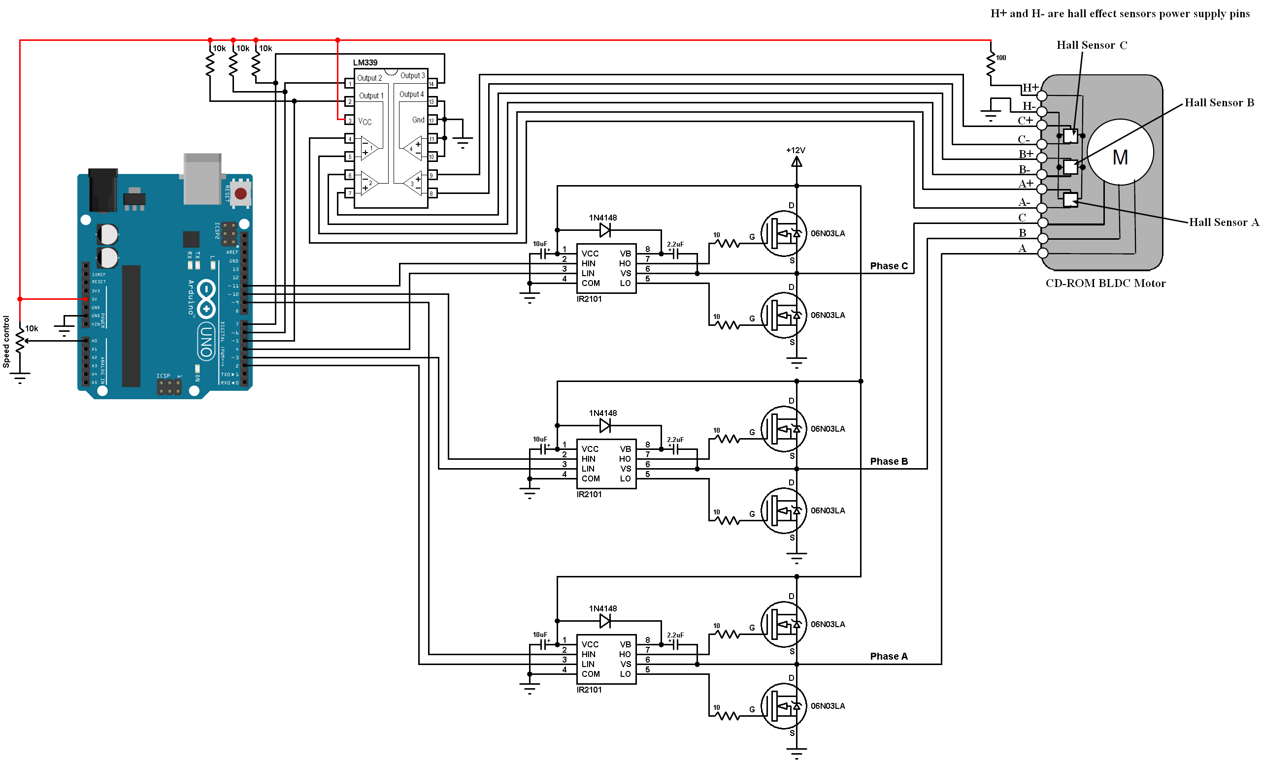
(All grounded terminals are connected together).
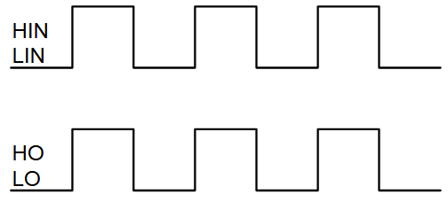
In the circuit there are three IR2101 gate driver ICs, each one is used to drive one high side mosfet and one low side mosfet, the switching between the high side and the low side is done according to the control lines which are: HIN and LIN. The figure below shows input and output timing diagram:
The used motor has 3 hall effect sensors as any sensored brushless motor, each hall effect sensor has 4 pins: VCC, GND, H+ and H-. The three sensors are supplied with +5V through 100 ohm resistor. Each sensor output (H+ and H-) is connected to a comparator (LM339) which therefore gives a single output as shown in the circuit diagram above.
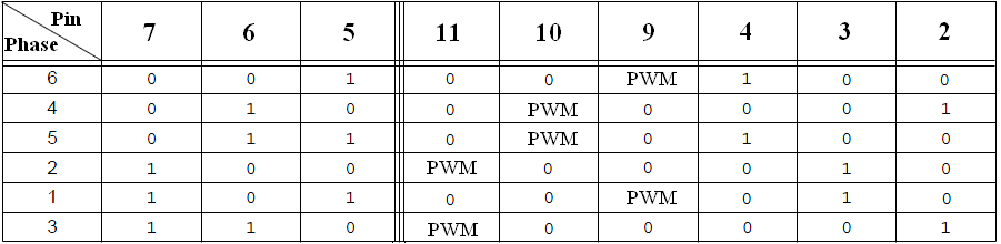
The 10k potentiometer is used to control the brushless DC motor speed, it is controlled using PWM technique (PWMing high sides only). At any time there is one active high side mosfet and one active low side mosfet, that means always there is one active PWM pin (Arduino pin 9, 10 or 11).
The table below summarizes the active Arduino pins according to the hall effect senors states (pins: 5, 6, and 7):
Sensorled BLDC motor control with Arduino code:
Arduino pins 9, 10 and 11 can generate PWM signals where pin 9 and pin 10 are related with Timer1 module (OC1A and OC1B) and pin 11 is related with Timer2 module (OC2A). Both Timer modules are configured to generate a PWM signal with a frequency of 31KHz and a resolution of 8 bits. The duty cycles of the PWM signals are updated after reading analog data from channel 0 (Arduino pin A0) by writing to their registers (OCR1A, OCR1B and OCR1A).
The ADC module is configured to read from channel 0 only.
Arduino interrupt on change is activated for pins 5, 6 and 7 (hall effect sensors inputs) for better commutation.
PORTB are Arduino uno pins: 8 … 13.
PORTD are Arduino uno pins: 0 … 7.
To fully understand the code, please read the ATmega328 datasheet!
1 2 3 4 5 6 7 8 9 10 11 12 13 14 15 16 17 18 19 20 21 22 23 24 25 26 27 28 29 30 31 32 33 34 35 36 37 38 39 40 41 42 43 44 45 46 47 48 49 50 51 52 53 54 55 56 57 58 59 60 61 62 63 64 65 66 67 68 69 70 71 72 73 74 75 76 77 78 79 80 81 82 83 84 85 86 87 88 89 90 91 92 93 94 95 96 97 98 99 100 101 102 103 104 105 106 107 108 109 110 | /* * CD-ROM Sensored BLDC motor control using Arduino. * This is a free software with NO WARRANTY. * https://simple-circuit.com/ */ byte bldc_step, motor_speed; void setup() { DDRD |= 0x1C; // Configure pins 2, 3 and 4 as outputs PORTD = 0x00; DDRB |= 0x0E; // Configure pins 9, 10 and 11 as outputs PORTB = 0x31; // Timer1 module setting: set clock source to clkI/O / 1 (no prescaling) TCCR1A = 0; TCCR1B = 0x01; // Timer2 module setting: set clock source to clkI/O / 1 (no prescaling) TCCR2A = 0; TCCR2B = 0x01; // ADC module configuration ADMUX = 0x60; // Configure ADC module and select channel 0 ADCSRA = 0x84; // Enable ADC module with 16 division factor (ADC clock = 1MHz) // Pin change interrupt configuration PCICR = 4; // Enable pin change interrupt for pins 0 to 7 PCMSK2 = 0xE0; // Enable pin change interrupt for pins 5, 6 and 7 // BLDC motor first move bldc_step = (PIND >> 5) & 7; // Read hall effect sensors status (PIND: read from PORTD which is arduino pins 0..7) bldc_move(); // Move the BLDC motor (first move) } ISR (PCINT2_vect){ bldc_step = (PIND >> 5) & 7; // Read hall effect sensors status (PIND: read from PORTD which is arduino pins 0..7) bldc_move(); // Move the BLDC motor } void bldc_move(){ // BLDC motor commutation function switch(bldc_step){ case 1: AH_CL(); break; case 2: BH_AL(); break; case 3: BH_CL(); break; case 4: CH_BL(); break; case 5: AH_BL(); break; case 6: CH_AL(); break; default: PORTD = 0; break; } } void loop() { ADCSRA |= 1 << ADSC; // Start conversion while(ADCSRA & 0x40); // Wait for conversion complete motor_speed = ADCH; // Read ADC data (8 bits) SET_PWM_DUTY(motor_speed); } void AH_BL(){ PORTD &= ~0x14; PORTD |= 0x08; TCCR2A = 0; // Turn pin 9 (OC1A) PWM ON (pin 10 & pin 11 OFF) TCCR1A = 0x81; // } void AH_CL(){ PORTD &= ~0x0C; PORTD |= 0x10; TCCR2A = 0; // Turn pin 9 (OC1A) PWM ON (pin 10 & pin 11 OFF) TCCR1A = 0x81; // } void BH_CL(){ PORTD &= ~0x0C; PORTD |= 0x10; TCCR2A = 0; // Turn pin 10 (OC1B) PWM ON (pin 9 & pin 11 OFF) TCCR1A = 0x21; // } void BH_AL(){ PORTD &= ~0x18; PORTD |= 0x04; TCCR2A = 0; // Turn pin 10 (OC1B) PWM ON (pin 9 & pin 11 OFF) TCCR1A = 0x21; // } void CH_AL(){ PORTD &= ~0x18; PORTD |= 0x04; TCCR1A = 0; // Turn pin 11 (OC2A) PWM ON (pin 9 & pin 10 OFF) TCCR2A = 0x81; // } void CH_BL(){ PORTD &= ~0x14; PORTD |= 0x08; TCCR1A = 0; // Turn pin 11 (OC2A) PWM ON (pin 9 & pin 10 OFF) TCCR2A = 0x81; // } void SET_PWM_DUTY(byte duty){ OCR1A = duty; // Set pin 9 PWM duty cycle OCR1B = duty; // Set pin 10 PWM duty cycle OCR2A = duty; // Set pin 11 PWM duty cycle } |
Sensorled brushless DC motor control with Arduino video:
The video below shows a simple hardware circuit of the project.


Hello friend, first of all, thank you for sharing your project. I have one question:
Can 06N03LA N-type be replaced by IRFZ44N? Thank you
ISR (PCINT2_vect){
this is error in code any solution or correct code please
sir which software we can use to do its simulation
why this error ?
sketch_mar08a:47:17: error: conflicting declaration of C function ‘void loop(…)’
void loop() {
^
In file included from sketch\sketch_mar08a.ino.cpp:1:0:
C:\Users\jampy\AppData\Local\Arduino15\packages\arduino\hardware\avr\1.8.3\cores\arduino/Arduino.h:155:6: note: previous declaration ‘void loop()’
void loop(void);
^~~~
exit status 1
conflicting declaration of C function ‘void loop(…)’
Funciona perfecto. Sensores a 120 grados garantizan que no presente problemas de arranque.
Gracias mi viejo. Medellin, colombia
Can i use this on a 48V BLDC motor, with a higher rating MOSFET??
Hi, I am wondering what is the purpose of
PORTB = 0x31;at line 13? Thank youcan i change the pwm frequency to 12khz or 15 khz in case it happens..how to modify??? suggest me …
hi sir
i have bldc motor with 5 pins for the hall sensor connections how can i connect 8 pins to that 5 pin bldc motor
If you have a BLDC motor with 5 pins for the hall sensor it means that you their is two pins for vcc and gnd and three pins for the the signal so you don’t have to use an LM339 you can directly plug the three signal pins of your hall sensors on pin 7,6, 5 of your arduino.
How do you make break ?
Can u give ur contact number