This Arduino project shows how to control DC motor speed using full wave controlled rectifier.
The speed of the DC motor is controlled using a potentiometer (connected to the Arduino board) by varying the value of the firing angle ‘alpha’ of the bridge thyristors.
The bridge rectifier used in this project is an AC to DC converter which consists of two thyristors and two diodes (semi-converter).
Related Project:
Arduino 220V Full Wave Controlled Bridge Rectifier
Arduino DC motor control with bridge rectifier circuit:
The following image shows project circuit schematic diagram.
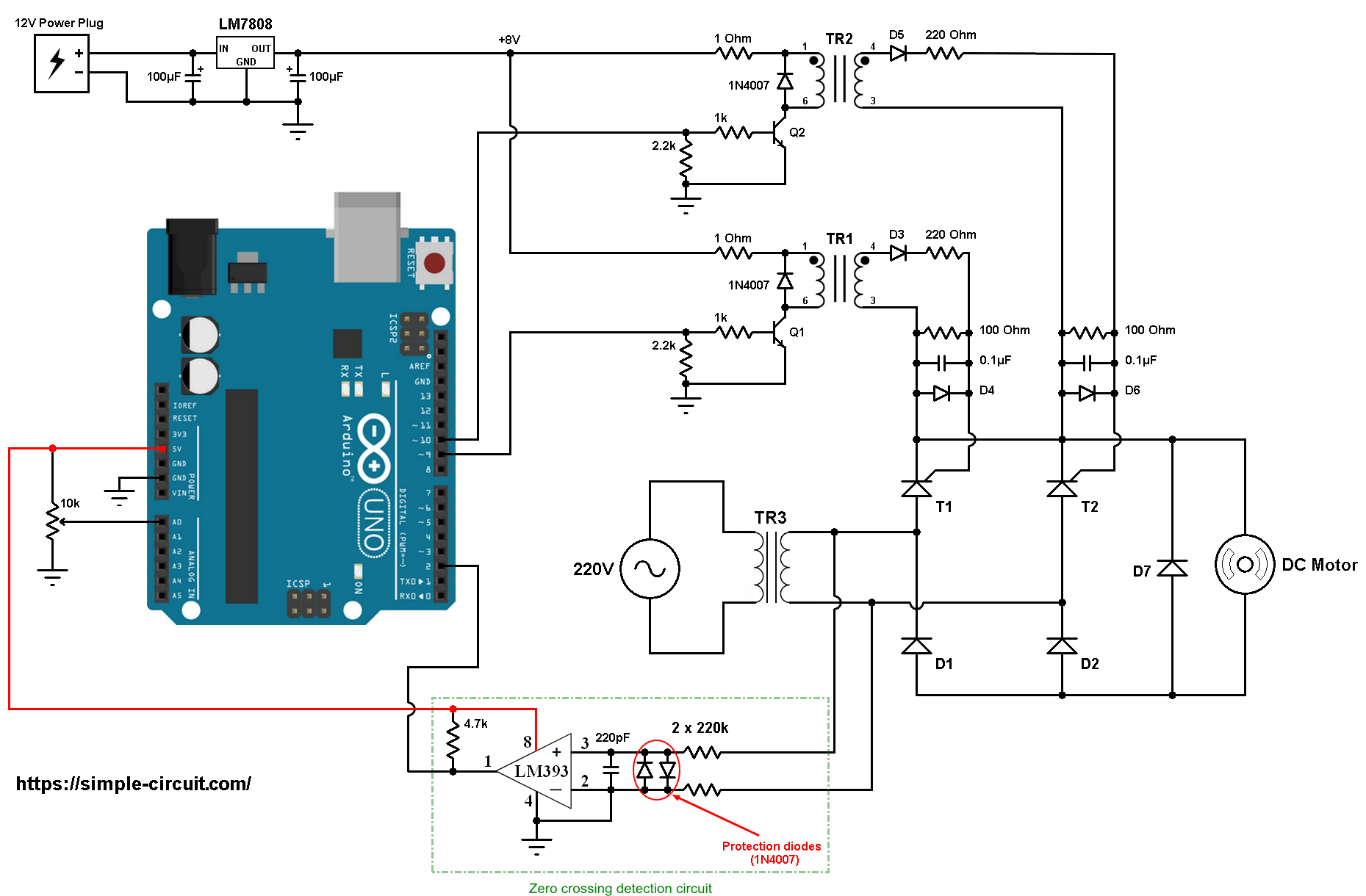
All the grounded terminals are connected together.
The input voltage of the circuit is 220/230V 50Hz alternating current (AC) from home outlet (single phase).
Transformer TR3 is a step down transformer that reduces the 220V into 12V (rms values) which is the same as DC motor nominal voltage.
In this project I used TYN1225 thyristor (datasheet) for T1 and T2. The diodes D1, D2 and D7 may be 1N4007 or equivalent.
The two transformers TR1 and TR2 are pulse transformers which are used for triggering the 2 thyristors T1 and T2. TR1 and TR2 are identical, their full name is: KMB472/101 (KMB472-101) from YHDC (datasheet).
The KMB472-101 transformer works with voltage of 8V, so to get 8V I used LM7808 voltage regulator. The LM7808 gives a regulated 8V from an external power source of 12V.
Each KMB472-101 transformer is connected to the LM7808 regulator output (8V) through a resistor of 1 ohm.
The diodes D3, D4, D5 and D6 are simple diodes, each one may be 1N4007 or 1N4148.
The two transistors Q1 and Q2 are NPN type, each one can be KSC2383 (datasheet) or equivalent. I’m using the KSC2383 in my hardware circuit!
Q1 and Q2 base terminals are respectively connected to Arduino pin 9 and pin 10 through 1k ohm resistor.
In this project I used the LM393 (dual comparator IC) for the zero crossing events detection. The two diodes (1N4007) which are connected between the non-inverting input (+) and the inverting input (-) of the comparator are used to limit the voltage between those pins. The output of the LM393 (or LM339) is an open collector, so I added the 4.7k ohm resistor there (between +5V and arduino pin 2). Also the comparator chip is supplied with +5V that comes from the Arduino board.
The non-inverting ( + ) and inverting ( – ) pins of the comparator are connected to the output of the transformer TR3, each one through 220k ohm resistor.
The firing angle alpha is controlled from the 10k ohm potentiometer (or variable resistor) where its output is connected to Arduino analog pin 0.
By varying the firing angle ‘alpha’ the speed of the motor also will vary, decreasing the firing angle increases the speed of the motor and increasing it will cause the motor to slow down.
Arduino DC motor control with bridge rectifier code:
Hints:
The frequency of the AC current is 50Hz which means the period is equal to 20 milliseconds, a half cycle is 10 milliseconds.
A zero degree firing angle alpha is represented by 0 ms, a 45° is 2.5 ms (2500 µs), a 90° is 5 ms (5000 µs) and 135° is 7.5ms (7500 µs). 180° is the full half wave width which is 10 ms (10000 µs).
For a 60Hz AC source, the period is 16.67ms and a half wave width is 8.33ms. So, a firing angle of 90° is represented by 4.167ms (4167µs).
The Arduino uno microcontroller (ATmega328P) has an ADC converter with 10-bit resolution, this means the digital output value may vary between 0 and 1023.
After reading from analog channel 0 the firing angle alpha is always between 0 and 9500 microseconds:
1 2 3 | alpha = ( 1023 - analogRead(pot) ) * 10; if(alpha > 9500) alpha = 9500; |
The output of the LM393 comparator is connected to Arduino digital pin 2 which is hardware external interrupt pin. Whenever there is a change of the state of that pin (from high to low or from low to high) it will interrupt the ATmega328P microcontroller which directly executes the function ZC_detect().
The interrupt is enabled using the following line:
1 | attachInterrupt(0, ZC_detect, CHANGE); // enable external interrupt (INT0) |
The two thyristors T1 and T2 are fired using two PWM signals (pulse train) which is generated using Timer1 module on pin 9 (for T1) and pin 10 (for T2) with frequency of 3.9375 kHz.
The duty cycle is set to 50, so we get a pulse train of 50µs (required by the pulse transformer YHDC KMB472-101):
1 2 3 4 | // PWM configuration OCR1A = 50; // set PWM1 duty cycle (about 50µs pulse, pin 9) OCR1B = 50; // set PWM2 duty cycle (about 50µs pulse, pin 10) TCCR1B = 0x02; // set Timer1 clock to CLKio/8 (get PWM frequency of 3.9375 kHz) |
A PWM is generated only on Arduino pin 9 when: TCCR1A = 0x81 and when TCCR1A = 0x21 a PWM signal is enabled on pin 10 only. Pins 9 and 10 PWMs are OFF when TCCR1A = 0.
The zero crossing event decides which thyristor will be triggered, if the 220V input voltage is at the positive cycle the LM393 comparator outputs high (logic 1) which means thyristor T1 will be fired (after the delay of the firing angle), otherwise T2 will be fired.
So, if the variable ZC is equal to 1 a PWM signal is generated on pin 9 (TCCR1A = 0x81) and if ZC is equal to 2 a PWM signal is generated on pin 10 (TCCR1A = 0x21):
1 | TCCR1A = (ZC == 1) ? 0x81 : 0x21; |
Full Arduino code:
1 2 3 4 5 6 7 8 9 10 11 12 13 14 15 16 17 18 19 20 21 22 23 24 25 26 27 28 29 30 31 32 33 34 35 36 37 38 39 40 41 42 43 44 45 46 47 48 49 50 51 52 53 54 55 56 57 58 59 60 61 62 63 64 65 66 67 68 69 70 71 72 73 | /************************************************************************* * * Full wave controlled bridge rectifier with Arduino. * This is a free software with NO WARRANTY. * http://simple-circuit.com/ * ************************************************************************/ #define pot A0 byte ZC = 0; uint16_t alpha; void setup(void) { pinMode(9, OUTPUT); // configure pin 9 as output pinMode(10, OUTPUT); // configure pin 10 as output digitalWrite(9, LOW); digitalWrite(10, LOW); // PWM configuration OCR1A = 50; // set PWM1 duty cycle (about 50µs pulse, pin 9) OCR1B = 50; // set PWM2 duty cycle (about 50µs pulse, pin 10) TCCR1B = 0x02; // set Timer1 clock to CLKio/8 (get PWM frequency of 3.9375 kHz) TCCR1A = 0; attachInterrupt(0, ZC_detect, CHANGE); // enable external interrupt (INT0) } // pin 2 debounce function bool debounce() { byte count = 0; for(byte i = 0; i < 5; i++) { if( digitalRead(2) ) count++; delayMicroseconds(5); } if(count > 3) return 1; return 0; } void ZC_detect() { TCCR1A = 0; // turn off PWM (pins 9 & 10) digitalWrite(9, LOW); digitalWrite(10, LOW); if( debounce() ) ZC = 1; else ZC = 2; } // main loop void loop() { if(ZC != 0) { if(alpha < 9500) { delayMicroseconds(alpha); TCCR1A = (ZC == 1) ? 0x81 : 0x21; } ZC = 0; alpha = ( 1023 - analogRead(pot) ) * 10; if(alpha > 9500) alpha = 9500; } } // end of code. |
The video below shows my simple hardware circuit:


