This post shows how to implement a simple temperature measurement station using Arduino UNO board and DS18B20 digital temperature sensor.
The Arduino reads temperature (in °C) from the DS18B20 sensor and print its value on ST7735 TFT display.
The ST7735 TFT used in this project is a color display which has a resolution of 128×160 pixel and it communicates with the master device using SPI (Serial Peripheral Interface) protocol.
The DS18B20 temperature sensor is a 3-pin electronic component (like a simple transistor) from Maxim (formerly Dallas) which uses 1-wire protocol to communicate with master device (microprocessor, microcontroller ….). Each DS18B20 device has a unique 64-bit serial code, which allows multiple DS18B20s to function on the same 1-wire bus and controlled with one master device.
The DS18B20 sensor provides 9-bit to 12-bit Celsius temperature measurement resolution (programmable resolution).
To see how to interface Arduino with ST7735 TFT display, visit the following post:
Arduino ST7735 1.8″ TFT display example
Hardware Required:
- Arduino board
- ST7735S (ST7735R) TFT screen
- DS18B20 temperature sensor —-> datasheet
- 5 x 1k ohm resistor
- 4.7k ohm resistor
- Breadboard
- Jumper wires
Arduino with DS18B20 sensor and ST7735 TFT display circuit:
The image below shows project circuit diagram.
The DS18B20 sensor has 3 pins (from right to left): VCC (or VDD), data and GND where:
VCC (VDD): sensor power supply pin, connected to Arduino 5V pin,
data pin: connected to Arduino analog pin 0 (A0) and
GND: connected to Arduino GND pin.
A pull-up resistor of 4.7k ohm is required because the DS18B20 output is open drain.
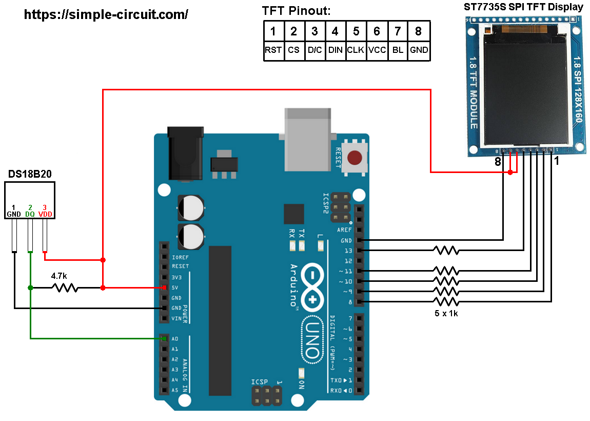
The ST7735S shown in project circuit diagram has 8 pins: (from right to left): RST (reset), CE (chip enable), DC (or D/C: data/command), DIN (data in), CLK (clock), VCC (5V or 3.3V), BL (back light) and Gnd (ground).
Normally the ST7735 display works with 3.3V only, but many boards of this display have a built-in 3.3V regulator (AMS1117 3V3) like the one shown in the circuit diagram. This regulator supplies the display controller with 3.3V from 5V source.
All Arduino UNO board output pins are 5V, connecting a 5V pin directly to the ST7735 display board may damage its controller circuit. To avoid that, I connected each control line of the display to the Arduino board through 1k ohm resistor.
So, the ST7735 display is connected to the Arduino board as follows (each one through 1k resistor):
RST pin is connected to Arduino digital pin 8,
CS pin is connected to Arduino digital pin 9,
D/C pin is connected to Arduino digital pin 10,
DIN pin is connected to Arduino digital pin 11,
CLK pin is connected to Arduino digital pin 13.
Arduino with ST7735 display and DS18B20 sensor code:
The following Arduino code requires 2 libraries from Adafruit Industries:
Adafruit ST7735 display library
Adafruit graphics library —-> direct link
After the download, go to Arduino IDE —> Sketch —> Include Library —> Add .ZIP Library … and browse for the .zip file (previously downloaded).
The same thing for the other library file.
The previous 2 libraries are included in the main code as follows:
1 2 | #include <Adafruit_GFX.h> // include Adafruit graphics library #include <Adafruit_ST7735.h> // include Adafruit ST7735 TFT library |
The ST7735 TFT display is connected to Arduino hardware SPI module pins (clock and data), the other pins which are: RST (reset), CS (chip select) and DC (data/command) are defined as shown below:
1 2 3 | #define TFT_RST 8 // TFT RST pin is connected to arduino pin 8 #define TFT_CS 9 // TFT CS pin is connected to arduino pin 9 #define TFT_DC 10 // TFT DC pin is connected to arduino pin 10 |
Functions used in the code:
bool ds18b20_start(): used to know if the DS18B20 sensor is correctly connected to the circuit, returns 1 if OK and 0 if error.
ds18b20_write_bit(bool value): writes (sends) 1 bit to the DS18B20 sensor, the bit is ‘value‘ which may be 1 or 0.
ds18b20_write_byte(byte value): writes 1 byte (8 bits) to the DS18B20 sensor, this function is based on the previous function. This function writes LSB first.
bool ds18b20_read_bit(void): reads 1 bit from the DS18B20 sensor, returns the read value (1 or 0).
byte ds18b20_read_byte(void): reads 1 byte from the DS18B20 sensor, this function is based on the previous function. This function reads LSB first.
bool ds18b20_read(int *raw_temp_value): reads the temperature raw data which is 16-bit long (two 8-bit registers), the data is stored in the variable raw_temp_value, returns 1 if OK and 0 if error.
The value of the temperature in degree Celsius is equal to the raw value divided by 16 (in case of 12-bit resolution). The default resolution of the DS18B20 is 12 bits ( ==> thermometer resolution = 0.0625°C).
Full Arduino code:
1 2 3 4 5 6 7 8 9 10 11 12 13 14 15 16 17 18 19 20 21 22 23 24 25 26 27 28 29 30 31 32 33 34 35 36 37 38 39 40 41 42 43 44 45 46 47 48 49 50 51 52 53 54 55 56 57 58 59 60 61 62 63 64 65 66 67 68 69 70 71 72 73 74 75 76 77 78 79 80 81 82 83 84 85 86 87 88 89 90 91 92 93 94 95 96 97 98 99 100 101 102 103 104 105 106 107 108 109 110 111 112 113 114 115 116 117 118 119 120 121 122 123 124 125 126 127 128 129 130 131 132 133 134 135 136 137 138 139 140 141 142 143 144 145 146 147 148 149 150 151 | /* * Arduino Thermometer using DS18B20 sensor and ST7735 color TFT (128x160 pixel) * This is a free software with NO WARRANTY. * http://simple-circuit.com/ */ #include <Adafruit_GFX.h> // include Adafruit graphics library #include <Adafruit_ST7735.h> // include Adafruit ST7735 TFT library #define TFT_RST 8 // TFT RST pin is connected to arduino pin 8 #define TFT_CS 9 // TFT CS pin is connected to arduino pin 9 #define TFT_DC 10 // TFT DC pin is connected to arduino pin 10 // initialize ST7735 TFT library Adafruit_ST7735 tft = Adafruit_ST7735(TFT_CS, TFT_DC, TFT_RST); // define DS18B20 data pin #define DS18B20_PIN A0 void setup(void) { tft.initR(INITR_BLACKTAB); // initialize a ST7735S chip, black tab tft.fillScreen(ST7735_BLACK); // fill screen with black color tft.drawFastHLine(0, 74, tft.width(), ST7735_BLUE); // draw horizontal blue line at position (0, 74) tft.setTextColor(ST7735_WHITE, ST7735_BLACK); // set text color to white and black background tft.setTextSize(1); // text size = 1 tft.setCursor(4, 30); // move cursor to position (4, 30) pixel tft.print("ARDUINO + ST7735 TFT"); tft.setCursor(16, 47); // move cursor to position (25, 47) pixel tft.print("+ DS18B20 SENSOR"); tft.setTextColor(ST7735_GREEN, ST7735_BLACK); // set text color to green and black background tft.setCursor(25, 95); // move cursor to position (25, 95) pixel tft.print("TEMPERATURE ="); tft.setTextSize(2); // text size = 2 tft.setTextColor(ST7735_CYAN, ST7735_BLACK); // set text color to cyan and black background } unsigned int ds18b20_temp; char _buffer[9]; // main loop void loop() { tft.setCursor(1, 115); if(ds18b20_read(&ds18b20_temp)) { if (ds18b20_temp & 0x8000) // if temperature < 0 { ds18b20_temp = ~ds18b20_temp + 1; // change temperature value to positive form sprintf(_buffer, "-%02u.%04u", (ds18b20_temp/16) % 100, (ds18b20_temp & 0x0F) * 625); } else { // otherwise (temperature >= 0) if (ds18b20_temp/16 >= 100) // if temperature >= 100 °C sprintf(_buffer, "%03u.%04u", ds18b20_temp/16, (ds18b20_temp & 0x0F) * 625); else // otherwise ( 0 <= temperature < 100) sprintf(_buffer, " %02u.%04u", ds18b20_temp/16, (ds18b20_temp & 0x0F) * 625); } tft.print(_buffer); tft.drawCircle(102, 117, 2, ST7735_CYAN); // print degree symbol ( ° ) tft.setCursor(108, 115); tft.print("C"); } else tft.print(" ERROR "); delay(1000); // wait a second } bool ds18b20_start() { bool ret = 0; digitalWrite(DS18B20_PIN, LOW); // send reset pulse to the DS18B20 sensor pinMode(DS18B20_PIN, OUTPUT); delayMicroseconds(500); // wait 500 us pinMode(DS18B20_PIN, INPUT); delayMicroseconds(100); // wait to read the DS18B20 sensor response if (!digitalRead(DS18B20_PIN)) { ret = 1; // DS18B20 sensor is present delayMicroseconds(400); // wait 400 us } return(ret); } void ds18b20_write_bit(bool value) { digitalWrite(DS18B20_PIN, LOW); pinMode(DS18B20_PIN, OUTPUT); delayMicroseconds(2); digitalWrite(DS18B20_PIN, value); delayMicroseconds(80); pinMode(DS18B20_PIN, INPUT); delayMicroseconds(2); } void ds18b20_write_byte(byte value) { byte i; for(i = 0; i < 8; i++) ds18b20_write_bit(bitRead(value, i)); } bool ds18b20_read_bit(void) { bool value; digitalWrite(DS18B20_PIN, LOW); pinMode(DS18B20_PIN, OUTPUT); delayMicroseconds(2); pinMode(DS18B20_PIN, INPUT); delayMicroseconds(5); value = digitalRead(DS18B20_PIN); delayMicroseconds(100); return value; } byte ds18b20_read_byte(void) { byte i, value; for(i = 0; i < 8; i++) bitWrite(value, i, ds18b20_read_bit()); return value; } bool ds18b20_read(int *raw_temp_value) { if (!ds18b20_start()) // send start pulse return(0); ds18b20_write_byte(0xCC); // send skip ROM command ds18b20_write_byte(0x44); // send start conversion command while(ds18b20_read_byte() == 0); // wait for conversion complete if (!ds18b20_start()) // send start pulse return(0); // return 0 if error ds18b20_write_byte(0xCC); // send skip ROM command ds18b20_write_byte(0xBE); // send read command // read temperature LSB byte and store it on raw_temp_value LSB byte *raw_temp_value = ds18b20_read_byte(); // read temperature MSB byte and store it on raw_temp_value MSB byte *raw_temp_value |= (unsigned int)(ds18b20_read_byte() << 8); return(1); // OK --> return 1 } // end of code. |
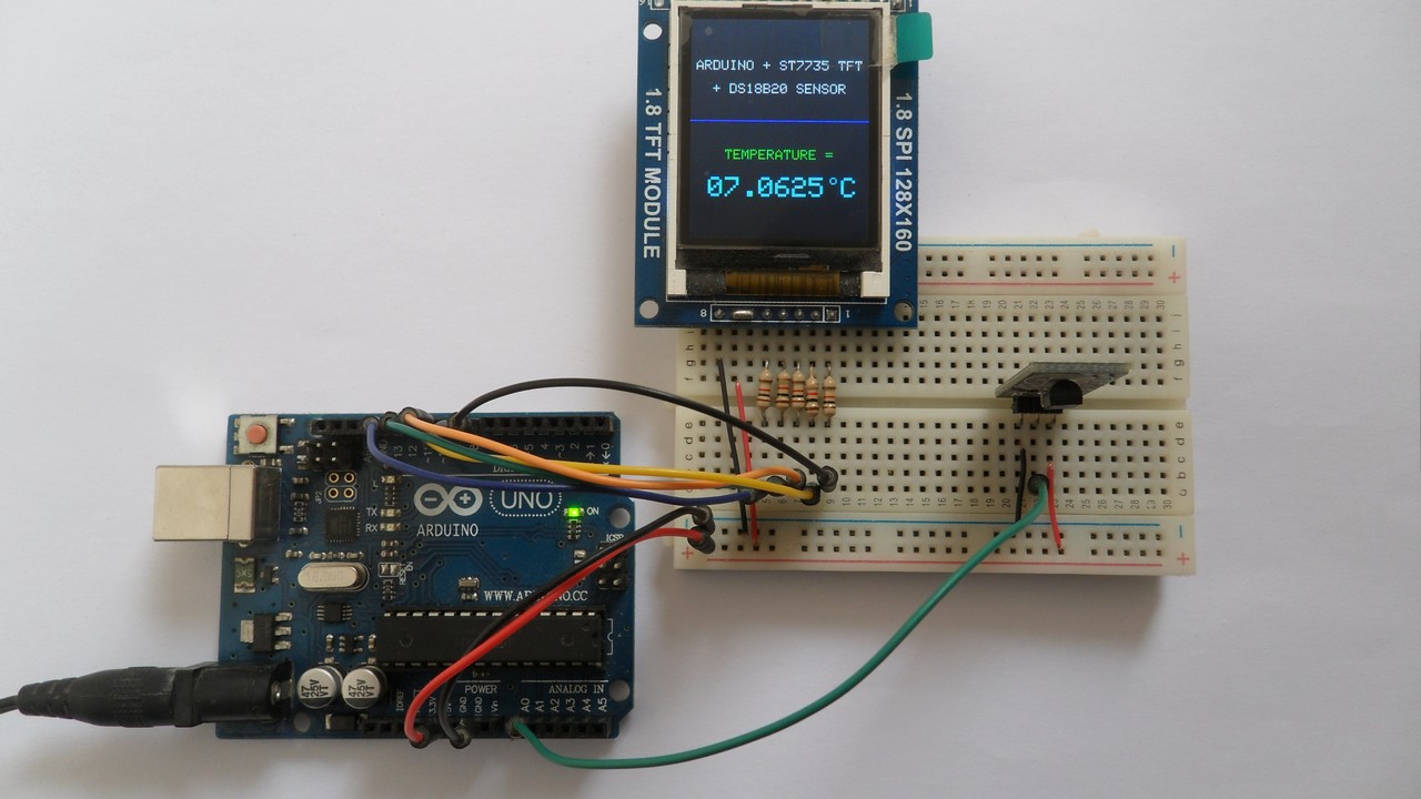
The following picture shows a protoboard circuit of the project:


Hi,
same here, can you give us a hint how to set or change the sensor resolution?
Hi, this code is very useful. As a total beginner I was able to run it with my Arduino uno and DS18B20.
Now I’m trying to round temperature value to one decimal place 0.0 Would it possible for you to give some tips how to do this?