After the interfacing of DS1307 real time clock IC with Arduino now I’m going to use DS3231 instead of the DS1307. Related topic link is below:
Arduino real time clock with DS1307
The DS3231 is also a low cost, easy to use and highly accurate real time clock IC which counts seconds, minutes, houres, day of the week, date, month and year. A battery can be connected to the DS3231 to keep the time running in case of main power failure. The DS3231 don’t need any oscillator because it has a built-in one.
Hardware Required:
- Arduino board
- DS3231 RTC board
- 1602 LCD screen
- 2 x push button
- 10K ohm variable resistor (or potentiometer)
- 330 ohm resistor
- 3V coin cell battery
- Breadboard
- Jumper wires
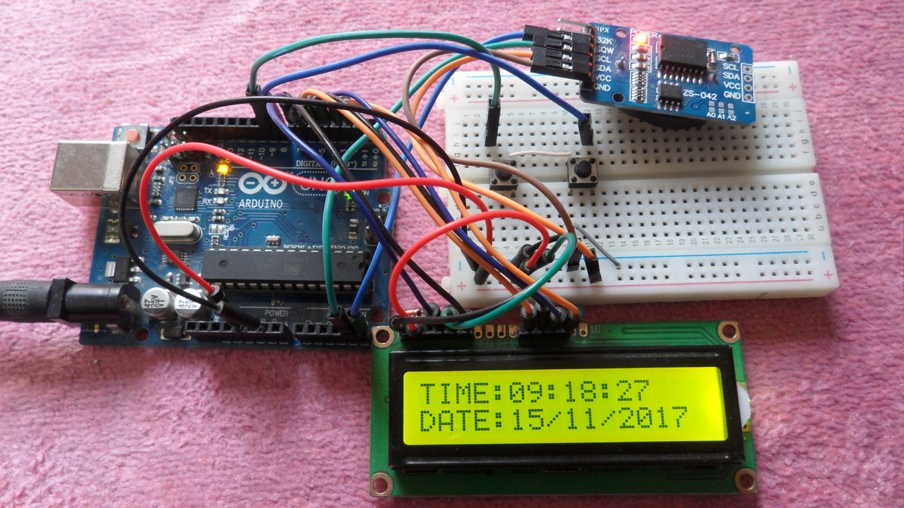
Arduino real time clock with DS3231 circuit:
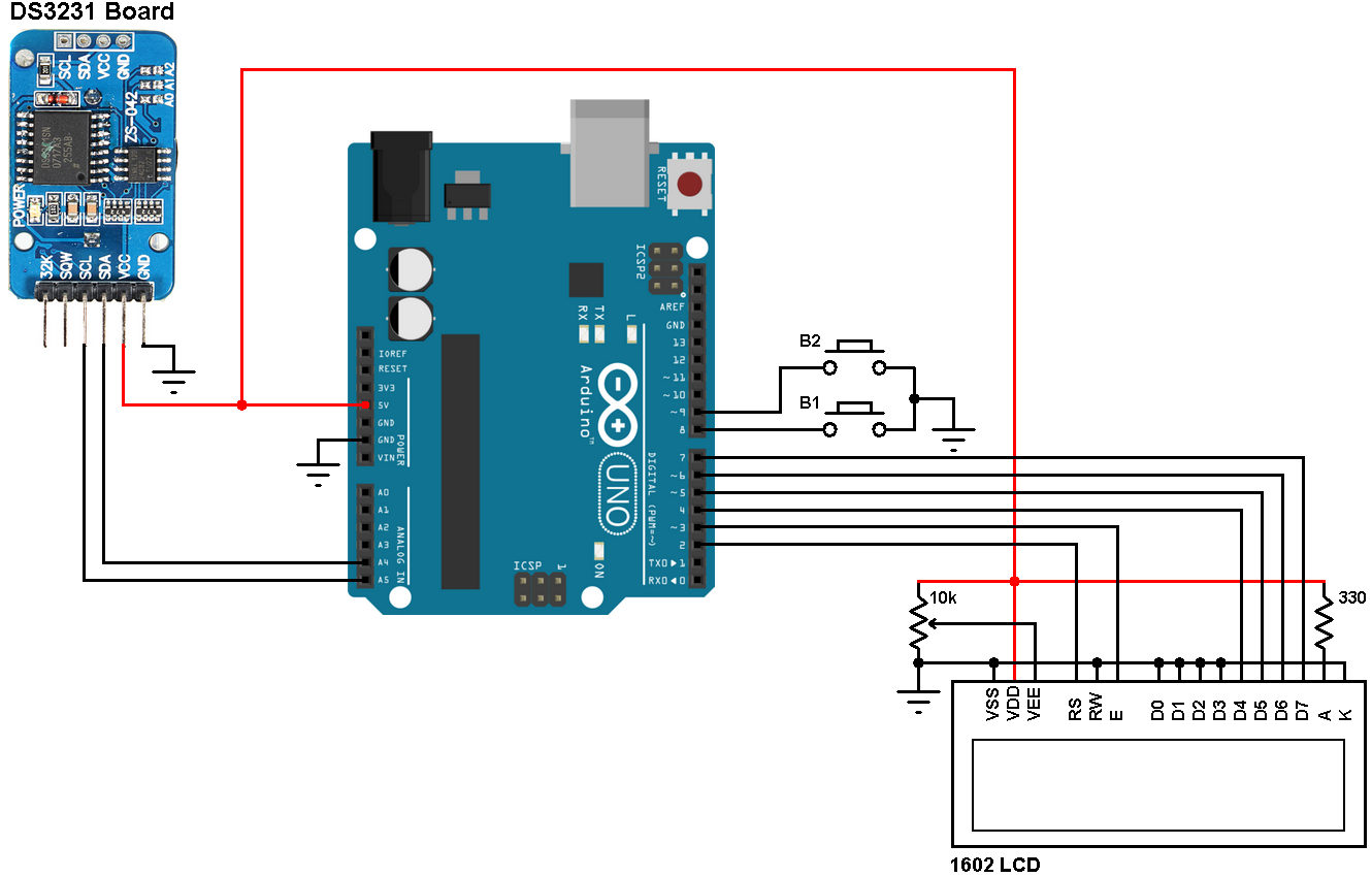
In the circuit there are 2 push buttons (B1 & B2) connected to pins 8 and 9 respectively, the two push buttons are used to set time date parameters (minutes, hours, date, month and year). Button B1 selects the parameter and B2 increments the selected parameter.
Arduino real time clock with DS3231 code:
The DS3231 Arduino code is similar to the DS1307 code and it works with both RTC chips.
The Arduino code below doesn’t use any library for the DS3231 RTC, the Wire library is for the communication between the Arduino and the DS3231 using I2C protocol.
The DS3231 works with BCD format only and to convert the BCD to decimal and vise versa I used the 2 lines below (example for minute):
// Convert BCD to decimal
minute = (minute >> 4) * 10 + (minute & 0x0F);
// Convert decimal to BCD
minute = ((minute / 10) << 4) + (minute % 10);
void DS3231_display() : displays time and calendar, before displaying time and calendar data are converted from BCD to decimal format.
void blink_parameter() : this small function works as a delay except that it is interrupted by the buttons B1 (connected to pin 8) and B2 (connected to pin 9). When called and without pressing any button the total time is 10 x 25ms = 250ms. With this function we can see the blinking of the selected parameter with a frequency of 2Hz. So a delay of 250ms comes after the print of the selected parameter and after that delay a 2 spaces is printed which makes the parameter disappears from the LCD and another 250ms delay comes after the print of the 2 spaces.
The complete code is below.
1 2 3 4 5 6 7 8 9 10 11 12 13 14 15 16 17 18 19 20 21 22 23 24 25 26 27 28 29 30 31 32 33 34 35 36 37 38 39 40 41 42 43 44 45 46 47 48 49 50 51 52 53 54 55 56 57 58 59 60 61 62 63 64 65 66 67 68 69 70 71 72 73 74 75 76 77 78 79 80 81 82 83 84 85 86 87 88 89 90 91 92 93 94 95 96 97 98 99 100 101 102 103 104 105 106 107 108 109 110 111 112 113 114 115 116 117 118 119 120 121 122 123 124 125 126 127 128 129 130 131 132 | // Real time clock and calendar with set buttons using DS3231 and Arduino // include LCD library code #include <LiquidCrystal.h> // include Wire library code (needed for I2C protocol devices) #include <Wire.h> // LCD module connections (RS, E, D4, D5, D6, D7) LiquidCrystal lcd(2, 3, 4, 5, 6, 7); void setup() { pinMode(8, INPUT_PULLUP); // button1 is connected to pin 8 pinMode(9, INPUT_PULLUP); // button2 is connected to pin 9 // set up the LCD's number of columns and rows lcd.begin(16, 2); Wire.begin(); // Join i2c bus } char Time[] = "TIME: : : "; char Calendar[] = "DATE: / /20 "; byte i, second, minute, hour, date, month, year; void DS3231_display(){ // Convert BCD to decimal second = (second >> 4) * 10 + (second & 0x0F); minute = (minute >> 4) * 10 + (minute & 0x0F); hour = (hour >> 4) * 10 + (hour & 0x0F); date = (date >> 4) * 10 + (date & 0x0F); month = (month >> 4) * 10 + (month & 0x0F); year = (year >> 4) * 10 + (year & 0x0F); // End conversion Time[12] = second % 10 + 48; Time[11] = second / 10 + 48; Time[9] = minute % 10 + 48; Time[8] = minute / 10 + 48; Time[6] = hour % 10 + 48; Time[5] = hour / 10 + 48; Calendar[14] = year % 10 + 48; Calendar[13] = year / 10 + 48; Calendar[9] = month % 10 + 48; Calendar[8] = month / 10 + 48; Calendar[6] = date % 10 + 48; Calendar[5] = date / 10 + 48; lcd.setCursor(0, 0); lcd.print(Time); // Display time lcd.setCursor(0, 1); lcd.print(Calendar); // Display calendar } void blink_parameter(){ byte j = 0; while(j < 10 && digitalRead(8) && digitalRead(9)){ j++; delay(25); } } byte edit(byte x, byte y, byte parameter){ char text[3]; while(!digitalRead(8)); // Wait until button (pin #8) released while(true){ while(!digitalRead(9)){ // If button (pin #9) is pressed parameter++; if(i == 0 && parameter > 23) // If hours > 23 ==> hours = 0 parameter = 0; if(i == 1 && parameter > 59) // If minutes > 59 ==> minutes = 0 parameter = 0; if(i == 2 && parameter > 31) // If date > 31 ==> date = 1 parameter = 1; if(i == 3 && parameter > 12) // If month > 12 ==> month = 1 parameter = 1; if(i == 4 && parameter > 99) // If year > 99 ==> year = 0 parameter = 0; sprintf(text,"%02u", parameter); lcd.setCursor(x, y); lcd.print(text); delay(200); // Wait 200ms } lcd.setCursor(x, y); lcd.print(" "); // Display two spaces blink_parameter(); sprintf(text,"%02u", parameter); lcd.setCursor(x, y); lcd.print(text); blink_parameter(); if(!digitalRead(8)){ // If button (pin #8) is pressed i++; // Increament 'i' for the next parameter return parameter; // Return parameter value and exit } } } void loop() { if(!digitalRead(8)){ // If button (pin #8) is pressed i = 0; hour = edit(5, 0, hour); minute = edit(8, 0, minute); date = edit(5, 1, date); month = edit(8, 1, month); year = edit(13, 1, year); // Convert decimal to BCD minute = ((minute / 10) << 4) + (minute % 10); hour = ((hour / 10) << 4) + (hour % 10); date = ((date / 10) << 4) + (date % 10); month = ((month / 10) << 4) + (month % 10); year = ((year / 10) << 4) + (year % 10); // End conversion // Write data to DS3231 RTC Wire.beginTransmission(0x68); // Start I2C protocol with DS3231 address Wire.write(0); // Send register address Wire.write(0); // Reset sesonds and start oscillator Wire.write(minute); // Write minute Wire.write(hour); // Write hour Wire.write(1); // Write day (not used) Wire.write(date); // Write date Wire.write(month); // Write month Wire.write(year); // Write year Wire.endTransmission(); // Stop transmission and release the I2C bus delay(200); // Wait 200ms } Wire.beginTransmission(0x68); // Start I2C protocol with DS3231 address Wire.write(0); // Send register address Wire.endTransmission(false); // I2C restart Wire.requestFrom(0x68, 7); // Request 7 bytes from DS3231 and release I2C bus at end of reading second = Wire.read(); // Read seconds from register 0 minute = Wire.read(); // Read minuts from register 1 hour = Wire.read(); // Read hour from register 2 Wire.read(); // Read day from register 3 (not used) date = Wire.read(); // Read date from register 4 month = Wire.read(); // Read month from register 5 year = Wire.read(); // Read year from register 6 DS3231_display(); // Diaplay time & calendar delay(50); // Wait 50ms } |
The following video shows project simulation using Proteus:
Downloads:
To be able to simulate this example, Proteus needs the Arduino library which can be downloaded from the link below. After extracting the files (ARDUINO.IDX and ARDUINO.LIB) put it in the Library folder (ex: C:\Program Files\Labcenter Electronics\Proteus 8 Professional\LIBRARY):
Download
Arduino + DS3231 + LCD Proteus simulation file download:
Download


Thank you so much for your kind words and heartfelt message. It’s truly inspiring to hear about your passion for exploring and experimenting with Arduino projects at the age of 82! Your lighthouse project with the elevator and the current clock project with servos sound fascinating and creative. It’s evident that you have a great enthusiasm for learning and applying new technologies.
Dear mister,
You have make a very fine program. On my age of 82 years I feel I like a little shild in concerning to you.
I have used this program to make a lighthouse with an elevator that go’s up every our and go down every half hour.
with so many sensors that I have used 2 NANO’s . Communication between them I used LDR’s one side and LED’s on the other side. It was a nice long program. The elevator works with a small stepper. Al this works verywell.
Now I use your program to make a clock with 2 servo’s. One for the minutes and one for the hours.
I use the minute-servo every 5 minutes till 30 minutes and than go’s back to 0.
Allso the hours, every hour forward till 12 and than back to 0.
I use sinds 2006 the arduino, but as I see on internet all the young peoples I fiel myself as a baby and will learn so mutch in a sort time that I have. But I’am very happy that I find very smart people like you on the internet.
Thank you and again: Thank you very much for your terrific website.
With our best regards, F. Muller, The Netherlands.
Thank you so much Mr.Muller, you wrote a truly encouraging and motivating words, you are really building an interesting projects.
Thanks again and best wishes from me.
what to i need to decrease a selected parameter?
Great work man ! Lot info to learn from that code.
Thank you so much !
Is there a way to have the clock extended to display 10ths of a second?
This one works also with my LCD type mentioned above. But the delay is to much long and not equivalent with the real time clock’s second speed.
Please help me.
I didn’t get 1603 display on proteus ,how can I correct with LCD having no pin A and K?
hello how i convert this LCD to seven segment display with date and time..please reply sir
You’ve to do some modifications to fit the 7-segment display!
I too need the same thing for 7-segment display. Thanks.
This is what i looking for.
I used Arduino nano and all ok.
I had tried other (many)software but time and date lost every time that power is down.
Great work,thanks!
if(!digitalRead(8))
{ // If button (pin #8) is pressed
i++; // Increament ‘i’ for the next parameter
return parameter;
}
Sir can you please explain how this code runs when i value increments after 4. I mean after setting year how lcd goes on normal mode of date & time and blink effects disappears.