As a simple addition to the Arduino real time clock with alarms and temperature monitor project, I’m going to add an IR remote control function to the circuit. The remote control used in this project is a TV one (LG TV) which uses RC-5 protocol, this remote control will be used to set the real time clock time, calendar and alarms.
To see how to build an Arduino based real time clock with alarms and temperature monitor read the post below (with setup buttons):
Arduino real time clock with alarm and temperature monitor using DS3231
and to see how to decode IR remote controls with RC5 protocol with Arduino read the following topic:
Arduino RC5 IR remote control decoder
So this project is just a combination of the previous two projects.
We need to decode our remote control in order to know the code of each button because we’ve to add it in the Arduino software (code).
Hardware Required:
- Arduino board
- DS3231 RTC board — DS3231 datasheet
- 2004 LCD screen
- RC5 protocol IR remote control
- IR receiver
- LED
- 47µF capacitor
- 10K ohm variable resistor (or potentiometer)
- 2 x 330 ohm resistor
- 3V coin cell battery
- Breadboard
- Jumper wires
The circuit:
Project circuit schematic diagram is shown below.

The DS3231 board is supplied with 5V as the 2004 LCD and the IR receiver, this 5V comes from the Arduino board, there are 3 data lined connected between this board and the Arduino, SCL line is connected to analog pin 5, SDA is connected to analog pin 4 and INT line is connected to digital pin 2 which is the external interrupt pin of the Arduino (INT0). The DS3231 interrupts the microcontroller when there is an alarm (alarm1 or alarm2).
The IR receiver has 3 pins: GND, VCC and OUT where the OUT pin is connected to Arduino pin 3 which is external interrupt pin (INT1).
The LED which is connected to Arduino pin 10 is used as an alarm indicator (alarm1 or alarm2), so if there is an alarm the DS3231 pulls down the INT pin which interrupts the microcontroller (ATmega328P) and the microcontroller turns the LED ON, here a button on the remote control turns both the LED and the occurred alarm OFF.
Arduino Code:
The Arduino code below doesn’t use any library for the DS3231.
By reading the datasheet of the DS3231 RTC the code will be more easier!
The remote control used in this project is a TV IR remote control with RC5 protocol, it’s the one shown below (used buttons are numbered):
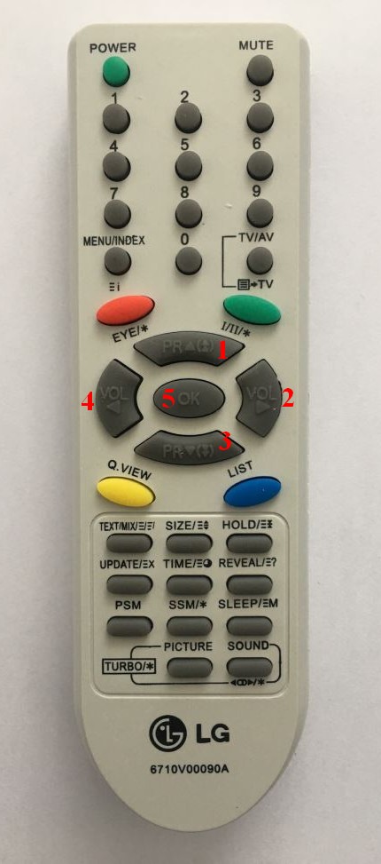
| Button number | Function | Code (hex format) |
| 1 | Increment | 0x20 |
| 2 | Set time and calendar | 0x10 |
| 3 | Decrement | 0x21 |
| 4 | Set alarms | 0x11 |
| 5 | Reset alarms | 0x25 |
Button #1 is used to increment the selected parameter (hours, minutes, day, date, month, year, alarm hours, alarm minutes and alarm status (ON and OFF)) and button #3 is used to decrement that parameter. Time and calendar parameters are selected with button #2 and alarms (alarm 1 and alarm 2) parameters are selected with button #4.
When alarm ( alarm 1 or alarm 2) the Arduino turns the LED ON, here button #5 turns the LED and the occurred alarm OFF.
Full Arduino code is below.
1 2 3 4 5 6 7 8 9 10 11 12 13 14 15 16 17 18 19 20 21 22 23 24 25 26 27 28 29 30 31 32 33 34 35 36 37 38 39 40 41 42 43 44 45 46 47 48 49 50 51 52 53 54 55 56 57 58 59 60 61 62 63 64 65 66 67 68 69 70 71 72 73 74 75 76 77 78 79 80 81 82 83 84 85 86 87 88 89 90 91 92 93 94 95 96 97 98 99 100 101 102 103 104 105 106 107 108 109 110 111 112 113 114 115 116 117 118 119 120 121 122 123 124 125 126 127 128 129 130 131 132 133 134 135 136 137 138 139 140 141 142 143 144 145 146 147 148 149 150 151 152 153 154 155 156 157 158 159 160 161 162 163 164 165 166 167 168 169 170 171 172 173 174 175 176 177 178 179 180 181 182 183 184 185 186 187 188 189 190 191 192 193 194 195 196 197 198 199 200 201 202 203 204 205 206 207 208 209 210 211 212 213 214 215 216 217 218 219 220 221 222 223 224 225 226 227 228 229 230 231 232 233 234 235 236 237 238 239 240 241 242 243 244 245 246 247 248 249 250 251 252 253 254 255 256 257 258 259 260 261 262 263 264 265 266 267 268 269 270 271 272 273 274 275 276 277 278 279 280 281 282 283 284 285 286 287 288 289 290 291 292 293 294 295 296 297 298 299 300 301 302 303 304 305 306 307 308 309 310 311 312 313 314 315 316 317 318 319 320 321 322 323 324 325 326 327 328 329 330 331 332 333 334 335 336 337 338 339 340 341 342 343 344 345 346 347 348 349 350 351 352 353 354 355 356 357 358 359 360 361 362 363 364 365 366 367 368 369 370 371 372 373 374 375 376 377 378 379 380 381 382 383 384 385 386 387 388 389 390 391 392 393 394 395 396 397 398 399 400 401 402 403 404 405 406 407 408 409 410 411 412 413 414 415 416 417 418 419 420 421 422 423 424 425 426 427 428 429 430 431 432 433 434 435 436 437 | /* Arduino real time clock and calendar with 2 alarm functions, temperature monitor and RC-5 IR remote control Read DS3231 RTC datasheet to understand the code DS3231 interrupt pin is connected to Arduino external interrupt pin (pin #2). */ // Define number of Timer1 ticks (with a prescaler of 1/8) #define short_time 1400 // Used as a minimum time for short pulse or short space ( ==> 700 us) #define med_time 2400 // Used as a maximum time for short pulse or short space ( ==> 1200 us) #define long_time 4000 // Used as a maximum time for long pulse or long space ( ==> 2000 us) // include LCD library code #include <LiquidCrystal.h> // include Wire library code (needed for I2C protocol devices) #include <Wire.h> // LCD module connections (RS, E, D4, D5, D6, D7) LiquidCrystal lcd(4, 5, 6, 7, 8, 9); const int alarm_pin = 10; // Alarms pin number void setup() { pinMode(alarm_pin, OUTPUT); digitalWrite(alarm_pin, LOW); // set up the LCD's number of columns and rows lcd.begin(20, 4); // Timer1 module configuration TCCR1A = 0; TCCR1B = 0; // Disable Timer1 module TCNT1 = 0; // Set Timer1 preload value to 0 (reset) TIMSK1 = 1; // enable Timer1 overflow interrupt Wire.begin(); // Join i2c bus attachInterrupt(1, RC5_read, CHANGE); // Enable external interrupt (INT1) attachInterrupt(0, Alarm, FALLING); // Enable external interrupt (INT0) } // RC5 remote control variables boolean rc5_ok = 0, toggle, last_toggle; byte rc5_state = 0, j; unsigned int rc5_code; // RTC Variables declaration bool alarm1_status, alarm2_status; char Time[] = " : : ", calendar[] = " / /20 ", alarm1[] = "A1: : :00", alarm2[] = "A2: : :00", temperature[] = "T: . C"; byte i, second, minute, hour, day, date, month, year, alarm1_minute, alarm1_hour, alarm2_minute, alarm2_hour, status_reg; void RC5_read() { unsigned int timer_value; if(rc5_state != 0){ timer_value = TCNT1; // Store Timer1 value TCNT1 = 0; // Reset Timer1 } switch(rc5_state){ case 0 : // Start receiving IR data (initially we're at the beginning of mid1) TCNT1 = 0; // Reset Timer1 TCCR1B = 2; // Enable Timer1 module with 1/8 prescaler ( 2 ticks every 1 us) rc5_state = 1; // Next state: end of mid1 j = 0; return; case 1 : // End of mid1 ==> check if we're at the beginning of start1 or mid0 if((timer_value > long_time) || (timer_value < short_time)){ // Invalid interval ==> stop decoding and reset rc5_state = 0; // Reset decoding process TCCR1B = 0; // Disable Timer1 module return; } bitSet(rc5_code, 13 - j); j++; if(j > 13){ // If all bits are received rc5_ok = 1; // Decoding process is OK toggle = bitRead(rc5_code, 11); // Toggle bit is bit number 11 rc5_code &= 0x07FF; // Remove the two start bits and the toggle bit from the code message detachInterrupt(1); // Disable external interrupt (INT1) return; } if(timer_value > med_time){ // We're at the beginning of mid0 rc5_state = 2; // Next state: end of mid0 if(j == 13){ // If we're at the LSB bit rc5_ok = 1; // Decoding process is OK bitClear(rc5_code, 0); // Clear the LSB bit toggle = bitRead(rc5_code, 11); // Toggle bit is bit number 11 rc5_code &= 0x07FF; detachInterrupt(1); // Disable external interrupt (INT1) return; } } else // We're at the beginning of start1 rc5_state = 3; // Next state: end of start1 return; case 2 : // End of mid0 ==> check if we're at the beginning of start0 or mid1 if((timer_value > long_time) || (timer_value < short_time)){ rc5_state = 0; // Reset decoding process TCCR1B = 0; // Disable Timer1 module return; } bitClear(rc5_code, 13 - j); j++; if(timer_value > med_time) // We're at the beginning of mid1 rc5_state = 1; // Next state: end of mid1 else // We're at the beginning of start0 rc5_state = 4; // Next state: end of start0 return; case 3 : // End of start1 ==> check if we're at the beginning of mid1 if((timer_value > med_time) || (timer_value < short_time)){ // Time interval invalid ==> stop decoding TCCR1B = 0; // Disable Timer1 module rc5_state = 0; // Reset decoding process return; } else // We're at the beginning of mid1 rc5_state = 1; // Next state: end of mid1 return; case 4 : // End of start0 ==> check if we're at the beginning of mid0 if((timer_value > med_time) || (timer_value < short_time)){ // Time interval invalid ==> stop decoding TCCR1B = 0; // Disable Timer1 module rc5_state = 0; // Reset decoding process return; } else // We're at the beginning of mid0 rc5_state = 2; // Next state: end of mid0 if(j == 13){ // If we're at the LSB bit rc5_ok = 1; // Decoding process is OK bitClear(rc5_code, 0); // Clear the LSB bit toggle = bitRead(rc5_code, 11); // Toggle bit is bit number 11 rc5_code &= 0x07FF; detachInterrupt(1); // Disable external interrupt (INT1) } } } ISR(TIMER1_OVF_vect) { // Timer1 interrupt service routine (ISR) rc5_state = 0; // Reset decoding process TCCR1B = 0; // Disable Timer1 module } void Alarm(){ digitalWrite(alarm_pin, HIGH); } void DS3231_read(){ // Function to read time & calendar data Wire.beginTransmission(0x68); // Start I2C protocol with DS3231 address Wire.write(0); // Send register address Wire.endTransmission(false); // I2C restart Wire.requestFrom(0x68, 7); // Request 7 bytes from DS3231 and release I2C bus at end of reading second = Wire.read(); // Read seconds from register 0 minute = Wire.read(); // Read minuts from register 1 hour = Wire.read(); // Read hour from register 2 day = Wire.read(); // Read day from register 3 date = Wire.read(); // Read date from register 4 month = Wire.read(); // Read month from register 5 year = Wire.read(); // Read year from register 6 } void alarms_read_display(){ // Function to read and display alarm1, alarm2 and temperature data byte control_reg, temperature_lsb; char temperature_msb; Wire.beginTransmission(0x68); // Start I2C protocol with DS3231 address Wire.write(0x08); // Send register address Wire.endTransmission(false); // I2C restart Wire.requestFrom(0x68, 11); // Request 11 bytes from DS3231 and release I2C bus at end of reading alarm1_minute = Wire.read(); // Read alarm1 minutes alarm1_hour = Wire.read(); // Read alarm1 hours Wire.read(); // Skip alarm1 day/date register alarm2_minute = Wire.read(); // Read alarm2 minutes alarm2_hour = Wire.read(); // Read alarm2 hours Wire.read(); // Skip alarm2 day/date register control_reg = Wire.read(); // Read the DS3231 control register status_reg = Wire.read(); // Read the DS3231 status register Wire.read(); // Skip aging offset register temperature_msb = Wire.read(); // Read temperature MSB temperature_lsb = Wire.read(); // Read temperature LSB // Convert BCD to decimal alarm1_minute = (alarm1_minute >> 4) * 10 + (alarm1_minute & 0x0F); alarm1_hour = (alarm1_hour >> 4) * 10 + (alarm1_hour & 0x0F); alarm2_minute = (alarm2_minute >> 4) * 10 + (alarm2_minute & 0x0F); alarm2_hour = (alarm2_hour >> 4) * 10 + (alarm2_hour & 0x0F); // End conversion alarm1[8] = alarm1_minute % 10 + 48; alarm1[7] = alarm1_minute / 10 + 48; alarm1[5] = alarm1_hour % 10 + 48; alarm1[4] = alarm1_hour / 10 + 48; alarm2[8] = alarm2_minute % 10 + 48; alarm2[7] = alarm2_minute / 10 + 48; alarm2[5] = alarm2_hour % 10 + 48; alarm2[4] = alarm2_hour / 10 + 48; alarm1_status = bitRead(control_reg, 0); // Read alarm1 interrupt enable bit (A1IE) from DS3231 control register alarm2_status = bitRead(control_reg, 1); // Read alarm2 interrupt enable bit (A2IE) from DS3231 control register if(temperature_msb < 0){ temperature_msb = abs(temperature_msb); temperature[2] = '-'; } else temperature[2] = ' '; temperature_lsb >>= 6; temperature[4] = temperature_msb % 10 + 48; temperature[3] = temperature_msb / 10 + 48; if(temperature_lsb == 0 || temperature_lsb == 2){ temperature[7] = '0'; if(temperature_lsb == 0) temperature[6] = '0'; else temperature[6] = '5'; } if(temperature_lsb == 1 || temperature_lsb == 3){ temperature[7] = '5'; if(temperature_lsb == 1) temperature[6] = '2'; else temperature[6] = '7'; } temperature[8] = 223; // Put the degree symbol lcd.setCursor(10, 0); lcd.print(temperature); // Display temperature lcd.setCursor(0, 2); lcd.print(alarm1); // Display alarm1 lcd.setCursor(17, 2); if(alarm1_status) lcd.print("ON "); // If A1IE = 1 print 'ON' else lcd.print("OFF"); // If A1IE = 0 print 'OFF' lcd.setCursor(0, 3); lcd.print(alarm2); // Display alarm2 lcd.setCursor(17, 3); if(alarm2_status) lcd.print("ON "); // If A2IE = 1 print 'ON' else lcd.print("OFF"); // If A2IE = 0 print 'OFF' } void calendar_display(){ // Function to display calendar switch(day){ case 1: strcpy(calendar, "Sun / /20 "); break; case 2: strcpy(calendar, "Mon / /20 "); break; case 3: strcpy(calendar, "Tue / /20 "); break; case 4: strcpy(calendar, "Wed / /20 "); break; case 5: strcpy(calendar, "Thu / /20 "); break; case 6: strcpy(calendar, "Fri / /20 "); break; case 7: strcpy(calendar, "Sat / /20 "); break; default: strcpy(calendar, "Sat / /20 "); } calendar[13] = year % 10 + 48; calendar[12] = year / 10 + 48; calendar[8] = month % 10 + 48; calendar[7] = month / 10 + 48; calendar[5] = date % 10 + 48; calendar[4] = date / 10 + 48; lcd.setCursor(0, 1); lcd.print(calendar); // Display calendar } void DS3231_display(){ // Convert BCD to decimal second = (second >> 4) * 10 + (second & 0x0F); minute = (minute >> 4) * 10 + (minute & 0x0F); hour = (hour >> 4) * 10 + (hour & 0x0F); date = (date >> 4) * 10 + (date & 0x0F); month = (month >> 4) * 10 + (month & 0x0F); year = (year >> 4) * 10 + (year & 0x0F); // End conversion Time[7] = second % 10 + 48; Time[6] = second / 10 + 48; Time[4] = minute % 10 + 48; Time[3] = minute / 10 + 48; Time[1] = hour % 10 + 48; Time[0] = hour / 10 + 48; calendar_display(); // Call calendar display function lcd.setCursor(0, 0); lcd.print(Time); // Display time } void Blink(){ byte k = 0; while((!rc5_ok || (rc5_code != 0x10) && (rc5_code != 0x11) && (rc5_code != 0x20) && (rc5_code != 0x21)) && (k < 10)){ k++; delay(25); } } byte edit(byte x, byte y, byte parameter){ char text[3]; rc5_reset(); while(true){ if(rc5_ok && (rc5_code == 0x20 || rc5_code == 0x21)){ // If RC5 code received if(rc5_code == 0x20){ parameter++; if(((i == 0) || (i == 5)) && parameter > 23) // If hours > 23 ==> hours = 0 parameter = 0; if(((i == 1) || (i == 6)) && parameter > 59) // If minutes > 59 ==> minutes = 0 parameter = 0; if(i == 2 && parameter > 31) // If date > 31 ==> date = 1 parameter = 1; if(i == 3 && parameter > 12) // If month > 12 ==> month = 1 parameter = 1; if(i == 4 && parameter > 99) // If year > 99 ==> year = 0 parameter = 0; if(i == 7 && parameter > 1) // For alarms ON or OFF (1: alarm ON, 0: alarm OFF) parameter = 0; } if(rc5_code == 0x21){ if(((i == 0) || (i == 5)) && parameter < 1) parameter = 24; if(((i == 1) || (i == 6)) && parameter < 1) parameter = 60; if(i == 2 && parameter < 2) parameter = 32; if(i == 3 && parameter < 2) parameter = 13; if(i == 4 && parameter < 1) parameter = 100; if(i == 7 && parameter < 1) parameter = 2; parameter--; } lcd.setCursor(x, y); if(i == 7){ // For alarms ON & OFF if(parameter == 1) lcd.print("ON "); else lcd.print("OFF"); } else{ sprintf(text,"%02u", parameter); lcd.print(text); } } if(rc5_ok){ delay(200); rc5_reset(); } lcd.setCursor(x, y); lcd.print(" "); // Print two spaces if(i == 7) lcd.print(" "); // Print space (for alarms ON & OFF) Blink(); // Call Blink function lcd.setCursor(x, y); if(i == 7){ // For alarms ON & OFF if(parameter == 1) lcd.print("ON "); else lcd.print("OFF"); } else{ sprintf(text,"%02u", parameter); lcd.print(text); } Blink(); if(i >= 5){ DS3231_read(); DS3231_display(); } if(rc5_ok && last_toggle != toggle && ((rc5_code == 0x10 && i < 5) || (rc5_code == 0x11 && i >= 5))){ i++; // Increment 'i' for the next parameter return parameter; // Return parameter value and exit } } } void rc5_reset(){ rc5_ok = 0; // Reset decoding process rc5_state = 0; last_toggle = toggle; // Save toggle bit attachInterrupt(1, RC5_read, CHANGE); // Enable external interrupt (INT1) } void loop() { if(rc5_ok){ // If RC5 code received if(rc5_code == 0x10){ // If clock/calendar set button code received i = 0; hour = edit(0, 0, hour); minute = edit(3, 0, minute); rc5_reset(); while(true){ if(rc5_ok && (rc5_code == 0x20)){ // If button up button code received day++; // Increment day if(day > 7) day = 1; calendar_display(); // Call display_calendar function lcd.setCursor(0, 1); lcd.print(calendar); // Display calendar } if(rc5_ok){ delay(200); rc5_reset(); } lcd.setCursor(0, 1); lcd.print(" "); // Print 3 spaces Blink(); lcd.setCursor(0, 1); lcd.print(calendar); // Print calendar Blink(); // Call Blink function if(rc5_ok && last_toggle != toggle && (rc5_code == 0x10)) // If button B1 is pressed break; } date = edit(4, 1, date); // Edit date month = edit(7, 1, month); // Edit month year = edit(12, 1, year); // Edit year // Convert decimal to BCD minute = ((minute / 10) << 4) + (minute % 10); hour = ((hour / 10) << 4) + (hour % 10); date = ((date / 10) << 4) + (date % 10); month = ((month / 10) << 4) + (month % 10); year = ((year / 10) << 4) + (year % 10); // End conversion // Write time & calendar data to DS3231 RTC Wire.beginTransmission(0x68); // Start I2C protocol with DS3231 address Wire.write(0); // Send register address Wire.write(0); // Reset sesonds and start oscillator Wire.write(minute); // Write minute Wire.write(hour); // Write hour Wire.write(day); // Write day Wire.write(date); // Write date Wire.write(month); // Write month Wire.write(year); // Write year Wire.endTransmission(); // Stop transmission and release the I2C bus } if(rc5_code == 0x11){ // If alarm set button code received i = 5; alarm1_hour = edit(4, 2, alarm1_hour); alarm1_minute = edit(7, 2, alarm1_minute); alarm1_status = edit(17, 2, alarm1_status); i = 5; alarm2_hour = edit(4, 3, alarm2_hour); alarm2_minute = edit(7, 3, alarm2_minute); alarm2_status = edit(17, 3, alarm2_status); alarm1_minute = ((alarm1_minute / 10) << 4) + (alarm1_minute % 10); alarm1_hour = ((alarm1_hour / 10) << 4) + (alarm1_hour % 10); alarm2_minute = ((alarm2_minute / 10) << 4) + (alarm2_minute % 10); alarm2_hour = ((alarm2_hour / 10) << 4) + (alarm2_hour % 10); // Write alarms data to DS3231 Wire.beginTransmission(0x68); // Start I2C protocol with DS3231 address Wire.write(7); // Send register address (alarm1 seconds) Wire.write(0); // Write 0 to alarm1 seconds Wire.write(alarm1_minute); // Write alarm1 minutes value to DS3231 Wire.write(alarm1_hour); // Write alarm1 hours value to DS3231 Wire.write(0x80); // Alarm1 when hours, minutes, and seconds match Wire.write(alarm2_minute); // Write alarm2 minutes value to DS3231 Wire.write(alarm2_hour); // Write alarm2 hours value to DS3231 Wire.write(0x80); // Alarm2 when hours and minutes match Wire.write(4 | alarm1_status | (alarm2_status << 1)); // Write data to DS3231 control register (enable interrupt when alarm) Wire.write(0); // Clear alarm flag bits Wire.endTransmission(); // Stop transmission and release the I2C bus } if(rc5_code == 0x25 && digitalRead(alarm_pin)){ // If rset alarm button code is received with alarm (Reset and turn OFF the alarm) digitalWrite(alarm_pin, LOW); // Turn OFF the alarm indicator Wire.beginTransmission(0x68); // Start I2C protocol with DS3231 address Wire.write(0x0E); // Send register address (control register) // Write data to control register (Turn OFF the occurred alarm and keep the other as it is) Wire.write(4 | (!bitRead(status_reg, 0) & alarm1_status) | ((!bitRead(status_reg, 1) & alarm2_status) << 1)); Wire.write(0); // Clear alarm flag bits Wire.endTransmission(); // Stop transmission and release the I2C bus } rc5_reset(); } DS3231_read(); // Read time and calendar parameters from DS3231 RTC alarms_read_display(); // Read and display alarms parameters DS3231_display(); // Display time & calendar delay(50); // Wait 50ms } // End of code |
The video below shows how a prototype circuit of the project:


Hi, I did your project but I have one problem. I cannot exit the alarm setup menu. It does not stop flashing. Where am I wrong?
Hi, the project is great. But I need a slightly different logic to work with. Have on and off time on alarm 1 and also on alarm 2 and control different outputs. Can you give me a hand?
Greetings friend!
Without bothering you, any news?
Oh! Thank you so much, I really liked the project!
How can I know? Thanks
Could you, kindly, do this same sketch for the NEC protocol with the IRremote library? Thanks
May be next days, I’ll try to do it.
Yes, it is with NEC protocol; I tried to modify, as I wrote above but, it did not work.
What do I have to modify, basically?
You’ve to understand both protocols and how to decode them!
Or, otherwise, how could I use your sketch with the NEC Protocol and the IRremote library? (if not much more work)
I think your remote control uses NEC protocol, you’ve to modify the code in order to work with your remote control.
This project (you’ve seen it before) may help you: “Arduino NEC IR remote control decoder”
I used two sketch to decode: IR remote_decoder and Find_Protocol; both sketches decoded the two controls exactly.
(NEC Remote Control)
1 > FF6897
2 > FF9867
3 > FFB04F
4 > FF30CF
5 > FF18E7
(SAMSUNG Remote Control) – This is LG Control detected as SAMSUNG.
1 > 808827D
2 > 80842BD
3 > 808C23D
4 > 80822DD
5 > 808A25D
I also looked at your site for the article about “Arduino NEC IR remote control decoder”;
I tried to adapt in my sketch, for example, where was “rc5”, I put “nec” and, for example, where was “attachInterrupt (1, RC5_read, CHANGE);” I put “attachInterrupt (1, remote_read, CHANGE);” but it did not work.
Like I said, the clock is working fine and the IR is decoded.
Is there a way for me to send you my sketch or, could you adapt your sketch to the NEC Protocol?
Once again, thank you very much
I experimented with an LG Control of a Mini System; I decoded the 5 keys (1 – 5) and replaced it in the sketch but it didn’t work!
I would love to wear this watch!
How did you decode your remote control (any links)?
That last question, I managed to solve, but the first not. I replaced all 5 codes of my control here: 0x10, 0x11, 0x20, 0x21 and 0x25. When I press the button on my controller, it turns on the red IR light, indicating that it is receiving Signal but does not execute the commands. My control is those little ones from china, branded KEYES. Any help, thank you
Actually I don’t know exactly which red LED are you talking about, the one shown in the circuit diagram is for alarm indicating and it’s not for IR signal receiving.
I think you’re using a remote control with NEC protocol (not RC5 protocol), so make sure you’re using the right remote control!
Yes, I am actually using a 17-button NEC Protocol Control, so what should I change in code to use this Control? Thanks
I didn’t have an answer to one question, I’m already asking another: what should be changed in the sketch to use a 20×4 I2C Display?
In place of: LiquidCrystal lcd (4, 5, 6, 7, 8, 9); I put: LiquidCrystal_I2C lcd (0x39,20,4); but nothing appears on the display (only backlight on).
It is one year old but anyway might help others.
If the address was right on I2C then adjust contrast setting of the LCD.
Firstly, thanks for the excellent project.
To use another type of IR remote control (like those small ones from china), just decode the necessary buttons and replace in the code where it appears 0x10, 0x11, 0x20, 0x21 and 0x25?