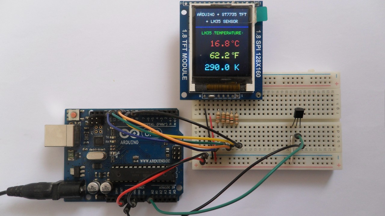
This Arduino project shows how to build a simple thermometer using LM35 analog temperature sensor.
In this project ST7735 TFT screen is used to display environment temperature in degree Celsius, Kelvin and degree Fahrenheit.
The ST7735 TFT is a color display which has a resolution of 128×160 pixel and it communicates with the master device using SPI (Serial Peripheral Interface) protocol.
To see how to interface Arduino with ST7735 TFT display, visit the following post:
Arduino ST7735 1.8″ TFT display example
The LM35 temperature sensor is a three pin device (VCC, OUT and GND) with an output voltage linearly related to Centigrade temperature. Since the LM35 output varies with dependent to the temperature, we need an ADC (Analog-to-Digital Converter) module to measure this voltage. Arduino UNO microcontroller (Microchip ATmega328P) has one ADC module with 10-bit resolution.
The LM35 output has linear +10mV/°C scale factor means the following:
If the output voltage = 10mV —> temperature = 1°C
If the output voltage = 100mV —> temperature = 10°C
If the output voltage = 200mV —> temperature = 20°C
If the output voltage = 370mV —> temperature = 37°C
and so on.
LM35 Futures (from datasheet):
- Calibrated Directly in ° Celsius (Centigrade)
- Linear + 10 mV/°C Scale Factor
- 0.5°C Ensured Accuracy (at +25°C)
- Rated for Full −55°C to +150°C Range
- Suitable for Remote Applications
- Low Cost Due to Wafer-Level Trimming
- Operates from 4 to 30 V
- Less than 60-μA Current Drain
- Low Self-Heating, 0.08°C in Still Air
- Nonlinearity Only ±¼°C Typical
- Low Impedance Output, 0.1 Ω for 1 mA Load
The ADC module converts analog data into digital data. The ATmega328P MCU has a 10-bit ADC module and a built-in reference voltage of 1.1V. Using the reference voltage should give better results.
Normally negative and positive references of the ADC module are VSS and VDD respectively, but VDD is not exactly equal to 5.00V, hence we should use the reference voltage (1.1V) as a positive reference of the ADC module.
Hardware Required:
- Arduino board
- ST7735S (ST7735R) TFT screen
- LM35 temperature sensor —-> datasheet
- 5 x 1k ohm resistor
- Breadboard
- Jumper wires
Arduino with ST7735 display and LM35 temperature sensor circuit:
The image below shows project circuit schematic diagram.
The LM35 sensor has 3 pins (from left to right):
Pin 1 is power supply pin, connected to Arduino 5V pin,
Pin 2: output pin, connected to Arduino analog pin 0 (A0),
Pin 3: GND (ground), connected to Arduino GND pin.
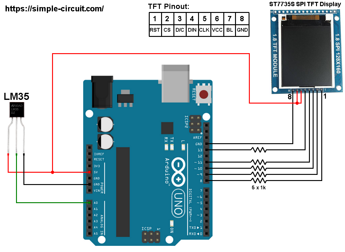
The ST7735S shown in project circuit diagram has 8 pins: (from right to left): RST (reset), CE (chip enable), DC (or D/C: data/command), DIN (data in), CLK (clock), VCC (5V or 3.3V), BL (back light) and Gnd (ground).
Normally the ST7735 display works with 3.3V only, but many boards of this display have a built-in 3.3V regulator (AMS1117 3V3) like the one shown in the circuit diagram. This regulator supplies the display controller with 3.3V from 5V source.
All Arduino UNO board output pins are 5V, connecting a 5V pin directly to the ST7735 display board may damage its controller circuit. To avoid that, I connected each control line of the display to the Arduino board through 1k ohm resistor.
So, the ST7735 display is connected to the Arduino board as follows (each one through 1k resistor):
RST pin is connected to Arduino digital pin 8,
CS pin is connected to Arduino digital pin 9,
D/C pin is connected to Arduino digital pin 10,
DIN pin is connected to Arduino digital pin 11,
CLK pin is connected to Arduino digital pin 13.
Arduino with ST7735 display and LM35 sensor code:
The following Arduino code requires 2 libraries from Adafruit Industries:
Adafruit ST7735 display library
Adafruit graphics library —-> direct link
After the download, go to Arduino IDE —> Sketch —> Include Library —> Add .ZIP Library … and browse for the .zip file (previously downloaded).
The same thing for the other library file.
The previous 2 libraries are included in the main code as follows:
1 2 | #include <Adafruit_GFX.h> // include Adafruit graphics library #include <Adafruit_ST7735.h> // include Adafruit ST7735 TFT library |
The ST7735 TFT display is connected to Arduino hardware SPI module pins (clock and data), the other pins which are: RST (reset), CS (chip select) and DC (data/command) are defined as shown below:
1 2 3 | #define TFT_RST 8 // TFT RST pin is connected to arduino pin 8 #define TFT_CS 9 // TFT CS pin is connected to arduino pin 9 #define TFT_DC 10 // TFT DC pin is connected to arduino pin 10 |
Reading voltage quantity using the ADC gives a number between 0 and 1023 (10-bit resolution), 0V is represented by 0 and 1.1V is represented by 1023 (ADC positive reference is 1.1V) . Converting back the ADC digital value is easy, we can use the following equation:
Voltage (in Volts) = ADC reading * 1.1 / 1023
Multiplying the previous result by 100 (LM35 scale factor is 10mV/°C = 0.01V/°C) gives the actual temperature:
Temperature( °C) = ADC reading * 0.1075 , or
Temperature( °C) = ADC reading / 9.3
where: 0.1075 = 100 * 1.1 / 1023 and 9.3 = 1 / 0.1075
To use the internal 1.1V reference I used the command: analogReference(INTERNAL);
In this example I used one number after the decimal point, multiplying the temperature by 10 gives the temperature in tenths degree Celsius (output value of “274” equals 27.4 °Celsius), so the final result is:
1 | tCelsius = 10 * analogRead(LM35_pin) / 9.3; |
The temperature in tenths degree Fahrenheit = (tenth °Celsius) x 9/5 +320 (because: °F = °Cx9/5 + 32) and the temperature in tenths Kelvin = (tenth °Celsius) + 2732 (because: K = °C + 273.16).
To get the actual value of each quantity we’ve to divide it by 10. The line below shows an example for temperature in Kelvin:
1 | sprintf(_buffer, "%03u.%1u K", tKelvin / 10, tKelvin % 10); |
We get the first 3 digits by dividing the tenths value by 10, and the tenths number (number after the decimal point) of the actual temperature value is equal to the reminder of that division (tenths value % 10).
The resolution of this thermometer is 0.1°C.
Full Arduino code:
1 2 3 4 5 6 7 8 9 10 11 12 13 14 15 16 17 18 19 20 21 22 23 24 25 26 27 28 29 30 31 32 33 34 35 36 37 38 39 40 41 42 43 44 45 46 47 48 49 50 51 52 53 54 55 56 57 58 59 60 61 62 63 64 65 66 67 68 69 70 71 72 73 74 75 76 77 78 79 80 81 82 83 84 85 | /* * Arduino with LM35 analog temperature sensor and ST7735 color TFT (128x160 pixel) * This is a free software with NO WARRANTY. * http://simple-circuit.com/ */ #include <Adafruit_GFX.h> // include Adafruit graphics library #include <Adafruit_ST7735.h> // include Adafruit ST7735 TFT library #define TFT_RST 8 // TFT RST pin is connected to arduino pin 8 #define TFT_CS 9 // TFT CS pin is connected to arduino pin 9 #define TFT_DC 10 // TFT DC pin is connected to arduino pin 10 // initialize ST7735 TFT library Adafruit_ST7735 tft = Adafruit_ST7735(TFT_CS, TFT_DC, TFT_RST); // define LM35 data pin connection #define LM35_pin A0 void setup(void) { analogReference(INTERNAL); // set positive reference voltage to 1.1V tft.initR(INITR_BLACKTAB); // initialize a ST7735S chip, black tab tft.fillScreen(ST7735_BLACK); // fill screen with black color tft.drawFastHLine(0, 44, tft.width(), ST7735_BLUE); // draw horizontal blue line at position (0, 44) tft.setTextColor(ST7735_WHITE, ST7735_BLACK); // set text color to white and black background tft.setTextSize(1); // text size = 1 tft.setCursor(4, 10); // move cursor to position (4, 10) pixel tft.print("ARDUINO + ST7735 TFT"); tft.setCursor(25, 27); // move cursor to position (25, 27) pixel tft.print("+ LM35 SENSOR"); tft.setTextColor(ST7735_GREEN, ST7735_BLACK); // set text color to green and black background tft.setCursor(15, 55); // move cursor to position (15, 55) pixel tft.print("LM35 TEMPERATURE:"); tft.setTextSize(2); // text size = 2 } // main loop void loop() { char _buffer[8]; // read analog voltage ( = tenths degree Celsius) // 9.3 = 1023/(1.1*100) int tCelsius = 10 * analogRead(LM35_pin) / 9.3; int tKelvin = tCelsius + 2732; // convert tenths °C to tenths Kelvin int tFahrenheit = tCelsius * 9/5 + 320 ; // convert tenths °C to tenths °Fahrenheit // print temperature in degree Celsius if (tCelsius >= 1000) // if temperature >= 100.0 °C sprintf(_buffer, "%03u.%1u", tCelsius / 10, tCelsius % 10); else sprintf(_buffer, " %02u.%1u", tCelsius / 10, tCelsius % 10); tft.setCursor(23, 77); tft.setTextColor(ST7735_RED, ST7735_BLACK); // set text color to red and black background tft.print(_buffer); tft.drawCircle(89, 79, 2, ST7735_RED); // print degree symbol ( ° ) tft.setCursor(95, 77); tft.print("C"); // print temperature in degree Fahrenheit if (tFahrenheit >= 1000) // if temperature >= 100.0 °F sprintf(_buffer, "%03u.%1u", tFahrenheit / 10, tFahrenheit % 10); else sprintf(_buffer, " %02u.%1u", tFahrenheit / 10, tFahrenheit % 10); tft.setCursor(23, 106); tft.setTextColor(ST7735_YELLOW, ST7735_BLACK); // set text color to yellow and black background tft.print(_buffer); tft.drawCircle(90, 108, 2, ST7735_YELLOW); // print degree symbol ( ° ) tft.setCursor(95, 106); tft.print("F"); // print temperature in Kelvin char _buffer1[8]; sprintf(_buffer, "%03u.%1u K", tKelvin/10, tKelvin % 10); tft.setCursor(23, 135); tft.setTextColor(ST7735_CYAN, ST7735_BLACK); // set text color to cyan and black background tft.print(_buffer); delay(1000); // wait a second } // end of code. |


