This Arduino project shows how to control unipolar stepper motor using Arduino UNO board and rotary encoder module.
The stepper motor used in this example is 28BYJ-48 (5V unipolar stepper motor) which usually comes with its driver board.
To see how to easily control stepper motor with Arduino, visit this post:
Arduino Unipolar Stepper Motor Control
In this project I used the rotary encoder shown below:
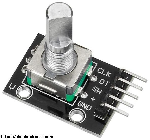
The rotary encoder module has 5 pins: GND, + (+5V or 3.3V), SW (push button), DT (pin B) and CLK (pin A).
As an addition to the rotary encoder there is a push button and three pull up resistors for pins SW, DT and CLK of 10k ohm. With the three pull-up resistors, the normal state of each terminal is logic high.
The rotary encoder generates (when rotating) two square waves on pins A (CLK) and B (DT) with 90° out of phase as shown in the figure below:
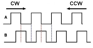
Since the normal state of pin A (CLK) and pin B (DT) are logic high we’ve to detect falling (transition from high to low) of one of them, here pin A is used to detect the movement of the rotary encoder in both directions (falling of pin A signal). Direction of rotation can be detected by knowing the status of pin B, if pin B is logic high this means the direction of rotation is clockwise (CW), and if pin B is logic low this means the direction of rotation is counter clockwise (CCW).
Hardware Required:
- Arduino UNO board
- 28BYJ-48 stepper motor (with ULN2003A driver board)
- Rotary encoder module
- 5V power source
- Bread board
- Jumper wires
Stepper motor control with Arduino and rotary encoder circuit:
Project circuit schematic diagram is shown below.

The stepper motor is connected to the ULN2003A board which is supplied with external power source of 5V. The control lines (IN1, IN2, IN3 and IN4) of this board are connected to the Arduino as:
IN1 to Arduino pin 11,
IN2 to Arduino pin 10,
IN3 to Arduino pin 9,
IN4 to Arduino pin 8.
The rotary encoder module has 5 pins: GND, + , SW, DT (pin B or data pin) and CLK (pin A or clock pin) where:
GND is connected to Arduino GND pin,
+ is connected to Arduino 5V pin,
SW is push button pin, not used in this example,
DT is connected to Arduino analog pin 5 (A5),
CLK is connected to Arduino analog pin 4 (A4).
Stepper motor control with Arduino and joystick code:
In this example I used Arduino stepper motor library (built-in) which simplifies the code, it’s included in the code using the following line:
1 | #include <Stepper.h> |
The stepper motor which I used in this project is 28BYJ-48, this motor is equipped with speed reducer of 1/64. The internal motor has 32 steps per one revolution which means the external shaft has 2048 steps per one revolution (64 x 32). Number of steps is defined in the code as shown below:
1 | #define STEPS 2048 |
and the connection of the control lines of the stepper motor with the Arduino are defined as:
1 2 3 4 5 6 7 8 | // define stepper motor control pins #define IN1 11 #define IN2 10 #define IN3 9 #define IN4 8 // initialize stepper library Stepper stepper(STEPS, IN4, IN2, IN3, IN1); |
The rotary encoder pin A (CLK) and pin B (DT) are connected to Arduino UNO pins A4 and A5 respectively. Both pins can be used to interrupt the Arduino microcontroller (ATmega328P) whenever there is a change in the state of at least one pin. The following lines are used to enable interrupt-on-change for pins A4 (PCINT12) and A5 (PCINT13):
1 2 3 | // pin change interrupt configuration PCICR = 2; // enable pin change interrupt for pins PCINT14..8 (Arduino A0 to A5) PCMSK1 = 0x30; // enable pin change interrupt for pins PCINT12 & PCINT13 (Arduino A4 & A5) |
Full Arduino code:
1 2 3 4 5 6 7 8 9 10 11 12 13 14 15 16 17 18 19 20 21 22 23 24 25 26 27 28 29 30 31 32 33 34 35 36 37 38 39 40 41 42 43 44 45 46 47 48 49 50 51 52 53 54 55 56 57 58 59 60 61 62 63 64 65 66 67 68 69 70 71 72 73 74 75 76 77 78 79 80 81 82 83 84 85 86 87 | /* * Arduino stepper motor control with rotary encoder. * This is a free software with NO WARRANTY. * http://simple-circuit.com/ */ // include Arduino stepper motor library #include <Stepper.h> // number of steps per one revolution is 2048 ( = 4096 half steps) #define STEPS 2048 // define stepper motor control pins #define IN1 11 #define IN2 10 #define IN3 9 #define IN4 8 // initialize stepper library Stepper stepper(STEPS, IN4, IN2, IN3, IN1); int8_t quad = 0; uint8_t previous_data; void setup() { stepper.setSpeed(10); // set stepper motor speed to 10 rpm // get rotary encoder state previous_data = digitalRead(A5) << 1 | digitalRead(A4); // pin change interrupt configuration PCICR = 2; // enable pin change interrupt for pins PCINT14..8 (Arduino A0 to A5) PCMSK1 = 0x30; // enable pin change interrupt for pins PCINT12 & PCINT13 (Arduino A4 & A5) } ISR (PCINT1_vect) // ISR for Arduino A4 (PCINT12) and A5 (PCINT13) pins { uint8_t current_data = digitalRead(A5) << 1 | digitalRead(A4); if( current_data == previous_data ) return; if( bitRead(current_data, 0) == bitRead(previous_data, 1) ) quad -= 1; else quad += 1; previous_data = current_data; } int8_t encoder_update(void) { int8_t val = 0; while(quad >= 4){ val += 1; quad -= 4; } while(quad <= -4){ val -= 1; quad += 4; } return val; } // main loop void loop() { int8_t stp = encoder_update(); while(stp != 0) { int8_t dir = (stp > 0) ? -1 : 1; stepper.step( 20 * dir ); stp += dir; stp += encoder_update(); } digitalWrite(IN1, LOW); digitalWrite(IN2, LOW); digitalWrite(IN3, LOW); digitalWrite(IN4, LOW); delay(100); } // end of code. |
The video below shows my simple hardware circuit test:


how do you change the speed?
Could someone give me the pin change interrupt (PCICR and PCMSK1) for 8 analog inputs using 4 encoders and 4 steppers. Thanks
Would you mind to make the connection between the motor and the encoder wirelessly sir?
@OGP Pointless???
Attach the rotary encoder to a steering wheel and the stepper to a boat engine and you have fly by wire steering, same if you add it to an accelerator pedal.
Put the encoder in your radio room and the use the stepper to control your antenna direction for ham radio or use the encoder to provide feedback from the antenna and the stepper to control a direction pointer for positional feedback.
I can think of a lot of applications for positional feedback.
I would like to use something similar to controll selectable 3x step/direction output for stepper drivers with 3 speeds for cnc jog pendant , any help would be appreciated
This is pointless,
if you grab encoder and turn the knob the stepper turns, why?
if you grab the shaft of the encoder and turn it you don’t need the arduino or the encoder or the stepper controller
and it does the exact same thing!
if you write some code where the encoder sets the rpm of the stepper and outputs the rpm to an oled and can change the rpm in increments of one rpm++ 1 or rpm–1 per pulse of the encoder then you have some usefull code for a project.
This was the most pointless comment I’ve ever seen. That’s for sure.
Hi, can you help me, I try to make the same with a A4988 motor controller, though I don’t understand the Arduino code..
Obviously, with the comment above, you show that you dont really have any clue of what is happening here, or how these things work. I can go into explaining it to you, but wont bother to waste my time.
As far as the actual project is concerned,
It is a good start, and it can be expanded on to make a really useful interface. Well done.