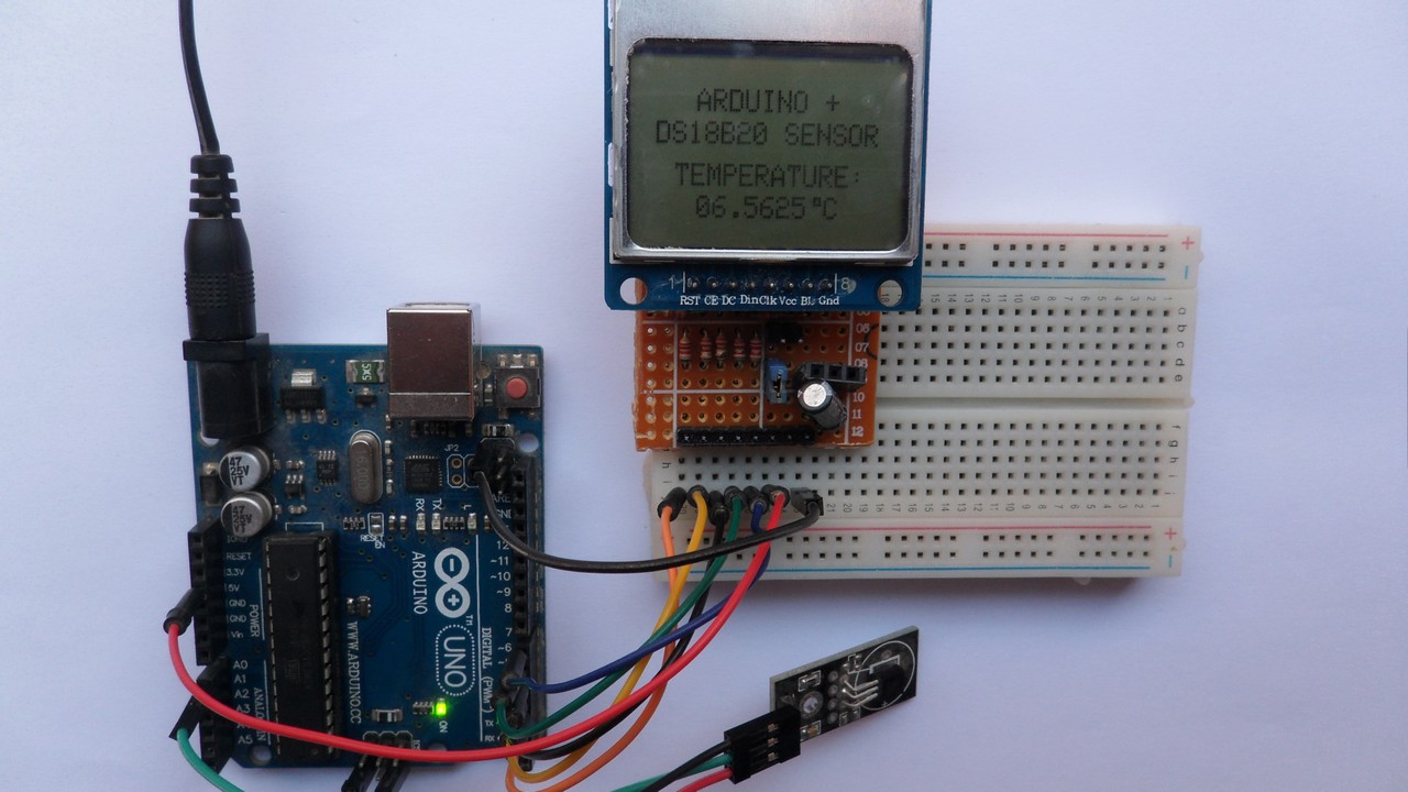
This Arduino tutorial shows how to build a temperature measurement station using DS18B20 sensor and NOKIA 5110 (NOKIA 3310) LCD screen.
The DS18B20 temperature sensor is a 3-pin electronic component (like a simple transistor) from Maxim (formerly Dallas) which uses 1-wire protocol to communicate with master device (microprocessor, microcontroller ….). Each DS18B20 device has a unique 64-bit serial code, which allows multiple DS18B20s to function on the same 1-wire bus and controlled with one master device.
The DS18B20 sensor provides 9-bit to 12-bit Celsius temperature measurement resolution (programmable resolution).
To see how to interface Arduino with Nokia 5110 LCD, visit the following post:
Interfacing Arduino with Nokia 5110 LCD
And to see how to interface Arduino with DS18B20 sensor for the first time, take a look at this post:
Digital thermometer using Arduino and DS18B20 sensor
Hardware Required:
- Arduino board
- Nokia 5110 LCD screen
- DS18B20 temperature sensor —-> datasheet
- 5 x 3.3k ohm resistor
- 5 x 2.2k ohm resistor
- 4.7k ohm resistor
- Breadboard
- Jumper wires
Arduino with DS18B20 sensor and Nokia 5110 LCD circuit:
The following image shows project circuit schematic diagram.
The DS18B20 sensor has 3 pins: VCC, data and GND where:
VCC: sensor power supply pin, connected to Arduino 5V pin,
data pin: connected to Arduino analog pin 0 (A0) and
GND: connected to Arduino GND pin.
A pull-up resistor of 4.7k ohm is required because the DS18B20 output is open drain.
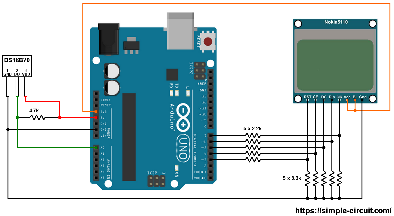
The Nokia 5110 LCD which is shown in the circuit diagram has 8 pins (from left to right): RST (reset), CE (chip enable), DC (or D/C: data/command), Din (data in), Clk (clock), VCC (3.3V), BL (back light) and Gnd (ground).
This LCD works with 3.3V only (power supply and control lines). The LCD module is supplied with 3.3V which comes from the Arduino board (VCC pin of the LCD is connected to Arduino 3.3V pin), BL pin is also connected to 3.3V.
All Arduino UNO board output pins are 5V, connecting a 5V pin to the Nokia 5110 LCD could damage its controller circuit.
To connect the Arduino to the LCD module and for the LCD safety, I used voltage divider for each line which means there are 5 voltage dividers. Each voltage divider consists of 2.2k and 3.3k resistors, this drops the 5V into 3V which is sufficient.
Nokia 5110 LCD pins are connected to Arduino UNO board as follows (each one through voltage divider):
RST (reset) pin is connected to Arduino digital pin 3
CE (chip enable) pin is connected to Arduino digital pin 4
DC (data/command) pin is connected to Arduino digital pin 5
DIN (data in) pin is connected to Arduino digital pin 6
CLK (clock) pin is connected to Arduino digital pin 7
VCC and BL are connected to Arduino 3V3 pin
GND is connected to Arduino GND pin.
Arduino with DS18B20 sensor and Nokia 5110 LCD code:
The Arduino code below doesn’t use any library for the DS18B20 sensor.
The following Arduino code requires 2 libraries from Adafruit Industries:
The first library is a driver for the Nokia 5110 LCD (PCD8544 controller) which can be installed from Arduino IDE library manager (Sketch —> Include Library —> Manage Libraries …, in the search box write “nokia” and install the one from Adafruit).
The second library is Adafruit graphics library which can be installed also from Arduino IDE library manager.
The previous 2 libraries can also be installed manually, download links are below:
Adafruit Nokia 5110 LCD library —-> direct link
Adafruit graphics library —-> direct link
After the download, go to Arduino IDE —> Sketch —> Include Library —> Add .ZIP Library … and browse for the .zip file (previously downloaded).
The same thing for the other library file.
In the code there are total of 3 libraries, they’re included in the code as follows:
1 2 3 | #include <SPI.h> // include SPI library #include <Adafruit_GFX.h> // include adafruit graphics library #include <Adafruit_PCD8544.h> // include adafruit PCD8544 (Nokia 5110) library |
Nokia 5110 LCD connection with the Arduino is configured as shown below:
1 2 | // Nokia 5110 LCD module connections (CLK, DIN, D/C, CS, RST) Adafruit_PCD8544 display = Adafruit_PCD8544(7, 6, 5, 4, 3); |
and the DS18B20 sensor data pin is defined as:
1 2 | // define DS18B20 data pin connection #define DS18B20_PIN A0 |
Functions used in the code:
bool ds18b20_start(): used to know if the DS18B20 sensor is correctly connected to the circuit, returns 1 if OK and 0 if error.
ds18b20_write_bit(bool value): writes (sends) 1 bit to the DS18B20 sensor, the bit is ‘value’ which may be 1 or 0.
ds18b20_write_byte(byte value): writes 1 byte (8 bits) to the DS18B20 sensor, this function is based on the previous function. This function writes LSB first.
bool ds18b20_read_bit(void): reads 1 bit from the DS18B20 sensor, returns the read value (1 or 0).
byte ds18b20_read_byte(void): reads 1 byte from the DS18B20 sensor, this function is based on the previous function. This function reads LSB first.
bool ds18b20_read(int *raw_temp_value): reads the temperature raw data which is 16-bit long (two 8-bit registers), the data is stored in the variable raw_temp_value, returns 1 if OK and 0 if error.
The value of the temperature in degree Celsius is equal to the raw value divided by 16 (in case of 12-bit resolution). The default resolution of the DS18B20 is 12 bits.
Full Arduino code:
1 2 3 4 5 6 7 8 9 10 11 12 13 14 15 16 17 18 19 20 21 22 23 24 25 26 27 28 29 30 31 32 33 34 35 36 37 38 39 40 41 42 43 44 45 46 47 48 49 50 51 52 53 54 55 56 57 58 59 60 61 62 63 64 65 66 67 68 69 70 71 72 73 74 75 76 77 78 79 80 81 82 83 84 85 86 87 88 89 90 91 92 93 94 95 96 97 98 99 100 101 102 103 104 105 106 107 108 109 110 111 112 113 114 115 116 117 118 119 120 121 122 123 124 125 126 127 128 129 130 131 132 133 134 135 136 137 138 139 140 141 142 143 144 145 146 147 148 149 150 151 152 153 154 155 156 157 158 159 160 161 162 | /* * Arduino Thermometer using DS18B20 sensor and Nokia 5110 LCD. * This is a free software with NO WARRANTY. * http://simple-circuit.com/ */ #include <SPI.h> // include SPI library #include <Adafruit_GFX.h> // include adafruit graphics library #include <Adafruit_PCD8544.h> // include adafruit PCD8544 (Nokia 5110) library // Nokia 5110 LCD module connections (CLK, DIN, D/C, CS, RST) Adafruit_PCD8544 display = Adafruit_PCD8544(7, 6, 5, 4, 3); // define DS18B20 data pin connection #define DS18B20_PIN A0 void setup() { // initialize the display display.begin(); // you can change the contrast around to adapt the display // for the best viewing! display.setContrast(50); display.clearDisplay(); // clear the screen and buffer display.display(); display.setTextSize(1); display.setTextColor(BLACK, WHITE); display.setCursor(15, 4); display.print("ARDUINO +"); display.setCursor(0, 14); display.print("DS18B20 SENSOR"); display.setCursor(7, 27); display.print("TEMPERATURE:"); display.display(); } // variable declarations int raw_temp; char *temp = "000.0000 C"; // main loop void loop() { if(ds18b20_read(&raw_temp)) { if(raw_temp & 0x8000) { // if the temperature is negative temp[0] = '-'; // put minus sign (-) raw_temp = abs(raw_temp); // absolute value } else { if((raw_temp >> 4) >= 100) // if the temperature >= 100 °C temp[0] = '1'; // put 1 of hundreds else // otherwise temp[0] = ' '; // put space ' ' } // put the first two digits (for ones and tens) temp[1] = ( (raw_temp >> 4) / 10 ) % 10 + '0'; // put tens digit temp[2] = (raw_temp >> 4) % 10 + '0'; // put ones digit // put the 4 fraction digits (digits after the decimal point) // why 625: because we're working with 12-bit resolution (default resolution) temp[4] = ( (raw_temp & 0x0F) * 625) / 1000 + '0'; // put tenths digit temp[5] = (((raw_temp & 0x0F) * 625) / 100 ) % 10 + '0'; // put hundredths digit temp[6] = (((raw_temp & 0x0F) * 625) / 10 ) % 10 + '0'; // put thousandths digit temp[7] = ( (raw_temp & 0x0F) * 625) % 10 + '0'; // put ten-thousandths digit display.setCursor(9, 37); display.print(temp); // print temperature display.drawRect(59, 37, 3, 3, BLACK); // print degree symbol ( ° ) display.display(); } else { display.setCursor(9, 37); display.print(" Error! "); display.display(); } delay(1000); // wait 1 second } bool ds18b20_start() { bool ret = 0; digitalWrite(DS18B20_PIN, LOW); // send reset pulse to the DS18B20 sensor pinMode(DS18B20_PIN, OUTPUT); delayMicroseconds(500); // wait 500 us pinMode(DS18B20_PIN, INPUT); delayMicroseconds(100); // wait to read the DS18B20 sensor response if (!digitalRead(DS18B20_PIN)) { ret = 1; // DS18B20 sensor is present delayMicroseconds(400); // wait 400 us } return(ret); } void ds18b20_write_bit(bool value) { digitalWrite(DS18B20_PIN, LOW); pinMode(DS18B20_PIN, OUTPUT); delayMicroseconds(2); digitalWrite(DS18B20_PIN, value); delayMicroseconds(80); pinMode(DS18B20_PIN, INPUT); delayMicroseconds(2); } void ds18b20_write_byte(byte value) { byte i; for(i = 0; i < 8; i++) ds18b20_write_bit(bitRead(value, i)); } bool ds18b20_read_bit(void) { bool value; digitalWrite(DS18B20_PIN, LOW); pinMode(DS18B20_PIN, OUTPUT); delayMicroseconds(2); pinMode(DS18B20_PIN, INPUT); delayMicroseconds(5); value = digitalRead(DS18B20_PIN); delayMicroseconds(100); return value; } byte ds18b20_read_byte(void) { byte i, value; for(i = 0; i < 8; i++) bitWrite(value, i, ds18b20_read_bit()); return value; } bool ds18b20_read(int *raw_temp_value) { if (!ds18b20_start()) // send start pulse return(0); ds18b20_write_byte(0xCC); // send skip ROM command ds18b20_write_byte(0x44); // send start conversion command while(ds18b20_read_byte() == 0); // wait for conversion complete if (!ds18b20_start()) // send start pulse return(0); // return 0 if error ds18b20_write_byte(0xCC); // send skip ROM command ds18b20_write_byte(0xBE); // send read command *raw_temp_value = ds18b20_read_byte(); // read temperature LSB byte and store it on raw_temp_value LSB byte *raw_temp_value |= (unsigned int)(ds18b20_read_byte() << 8); // read temperature MSB byte and store it on raw_temp_value MSB byte return(1); // OK --> return 1 } // end of code. |
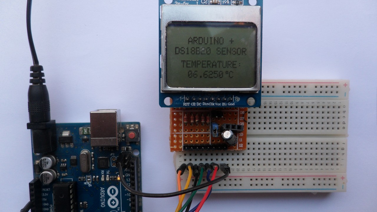
The following image shows the result of my protoboard circuit:
The video below shows Proteus simulation (note that simulation circuit is not the same as real hardware circuit, hardware circuit diagram is shown above):
Proteus simulation file download link is below, use version 8.6 or later to open it:
Arduino with Nokia 5110 LCD and DS18B20 sensor


