This post shows how to control a sensorless brushless DC (BLDC) motor using PIC16F887 microcontroller. The compiler used in this project is MikroElektronika mikroC PRO for PIC.
Basically there are two types of brushless motors: sensored and sensorless. Sensored BLDC motors come with three hall effect sensors which are used to detect (know) the position of the rotor (where it is located) at any moment, that’s why they called sensored.
The second type is: sensorless BLDC motors. Sensorless BLDC motor has no sensor to detect the rotor position, it has only 3 wires for power (3-phase). The commutation of sensorless BLDC motor is based on the BEMF (Back Electromotive Force) produced in the stator windings.
The main advantage of the sensorless BLDC motor control is lower system cost and the main disadvantage is the motor must be moving at minimum rate to produce sufficient BEMF to be sensed.
The following page contains a brief information about the BEMF technique:
Brushless DC motor control with PIC16F887 microcontroller
Components Required:
- PIC16F887 microcontroller – datasheet
- Brushless DC motor
- 6 x 06N03LA N-type mosfet (or equivalent) – datasheet
- 3 x IR2101 (or IR2101S) gate driver IC – datasheet
- 6 x 33k ohm resistor
- 3 x 10k ohm resistor
- 6 x 10 ohm resistor
- 3 x IN4148 diode
- 3 x 10uF capacitor
- 3 x 2.2uF capacitor
- 20 MHz crystal oscillator
- 2 x 22pF ceramic capacitor
- 10k ohm potentiometer
- 12V source
- 5V source
- Breadboard
- Jumper wires
Sensorless BLDC motor control with PIC16F887 circuit:
Project circuit schematic diagram is shown below.
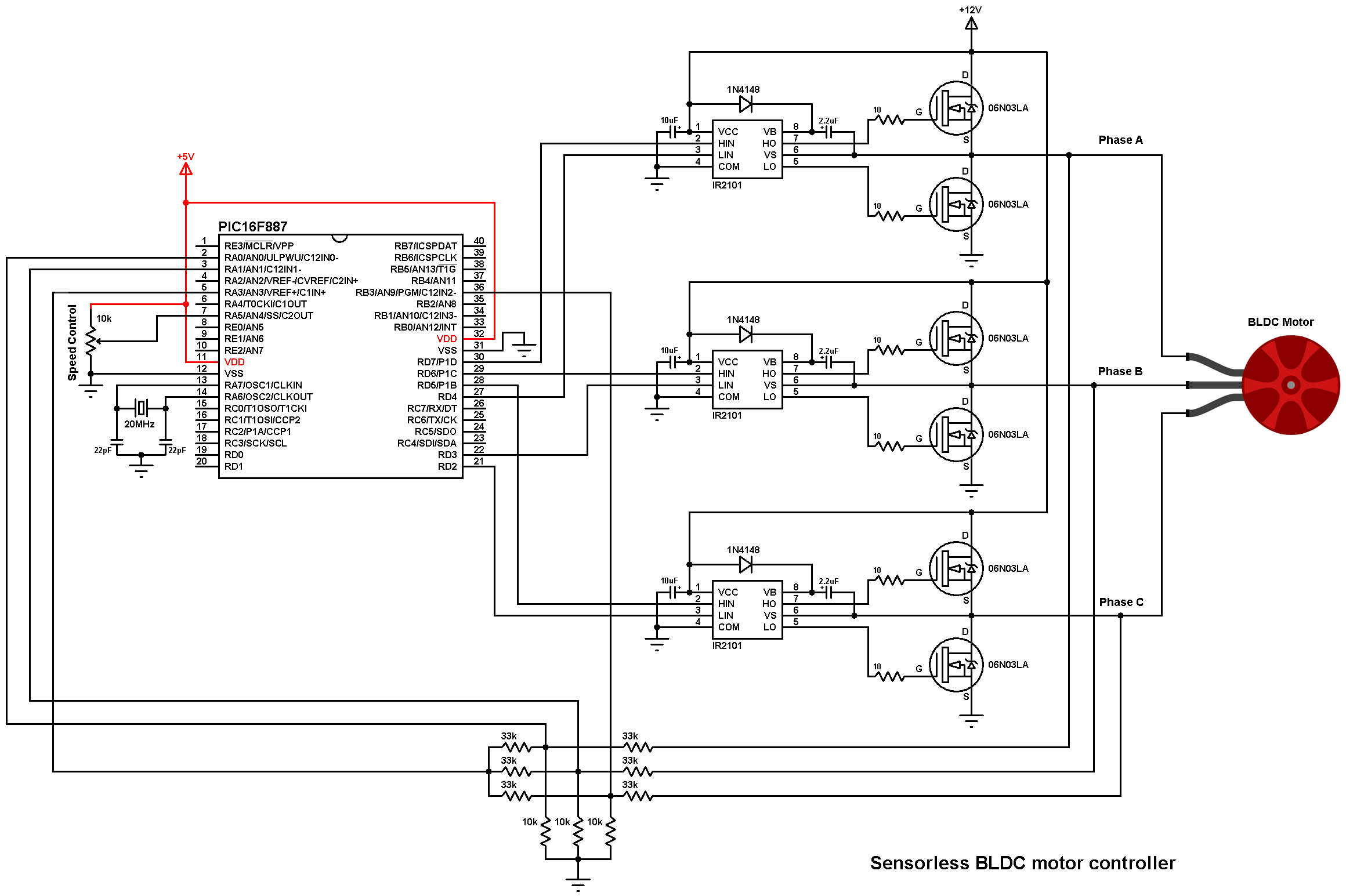
All grounded terminals are connected together.
Sensorless BLDC motor control with PIC16F887 code:
The following C code is for mikroC PRO for PIC compiler. Configuration words are:
CONFIG1 = 0x2CD2
CONFIG2 = 0x0700
Timer2 module is configured to give a PWM signal with frequency of 19.53 KHz and resolution of 10 bits (prescaler = 1 and preload value = 255).
PWM frequency and resolution can be calculated using the functions below (Fosc = 20 MHz):
PWM_freqency = Fosc/{[(PR2) + 1] * 4 * (TMR2 Prescaler Value)} = 19.53 KHz
Resolution = log[4(PR2 + 1)]/log(2) = 10 bits
mikroC PRO for PIC code:
1 2 3 4 5 6 7 8 9 10 11 12 13 14 15 16 17 18 19 20 21 22 23 24 25 26 27 28 29 30 31 32 33 34 35 36 37 38 39 40 41 42 43 44 45 46 47 48 49 50 51 52 53 54 55 56 57 58 59 60 61 62 63 64 65 66 67 68 69 70 71 72 73 74 75 76 77 78 79 80 81 82 83 84 85 86 87 88 89 90 91 92 93 94 95 96 97 98 99 100 101 102 103 104 105 106 107 108 109 110 111 112 113 114 115 116 117 118 119 120 121 122 123 124 125 126 127 128 129 130 131 132 133 134 135 136 137 138 139 140 141 142 143 144 145 146 147 148 149 150 151 152 153 154 155 156 157 158 159 160 161 162 163 164 165 166 167 168 169 170 171 172 173 174 175 176 177 | /************************************************************************************** Sensorless brushless DC ( BLDC ) motor control with PIC16F887 microcontroller C Code for mikroC PRO for PIC compiler Crystal oscillator used @ 20MHz Configuration words: CONFIG1 = 0x2CD2 CONFIG2 = 0x0700 This is a free software with NO WARRANTY. http://simple-circuit.com/ ***************************************************************************************/ #define PWM_MIN_DUTY 80 #define PWM_START_DUTY 200 #include <stdint.h> void AH_BL(); void AH_CL(); void BH_CL(); void BH_AL(); void CH_AL(); void CH_BL(); void bldc_move(); uint8_t bldc_step = 0; uint16_t motor_speed, i, j; void Interrupt() { // BEMF debounce int8_t j; for(j = 0; j < 10; j++) { if(bldc_step & 1) { if(!C1OUT_bit) j -= 1; } else { if(C1OUT_bit) j -= 1; } } bldc_move(); C1ON_bit = 1; // clear the mismatch condition C1IF_bit = 0; // Clear comparator 1 interrupt flag bit } void bldc_move() // BLDC motor commutation function { switch(bldc_step){ case 0: AH_BL(); CM1CON0 = 0xA2; // Sense BEMF C (pin RA3 positive, RB3 negative) break; case 1: AH_CL(); CM1CON0 = 0xA1; // Sense BEMF B (pin RA3 positive, RA1 negative) break; case 2: BH_CL(); CM1CON0 = 0xA0; // Sense BEMF A (pin RA3 positive, RA0 negative) break; case 3: BH_AL(); CM1CON0 = 0xA2; // Sense BEMF C (pin RA3 positive, RB3 negative) break; case 4: CH_AL(); CM1CON0 = 0xA1; // Sense BEMF B (pin RA3 positive, RA1 negative) break; case 5: CH_BL(); CM1CON0 = 0xA0; // Sense BEMF A (pin RA3 positive, RA0 negative) break; } bldc_step++; if(bldc_step >= 6) bldc_step = 0; } // set PWM1 duty cycle function void set_pwm_duty(uint16_t pwm_duty) { CCP1CON = ((pwm_duty << 4) & 0x30) | 0x0C; CCPR1L = pwm_duty >> 2; } // main function void main() { ANSEL = 0x10; // configure AN4 (RA5) pin as analog PORTD = 0; TRISD = 0; // ADC module configuration ADCON0 = 0xD0; // select analog channel 4 (AN4) ADFM_bit = 0; INTCON = 0xC0; // enable global and peripheral interrupts C1IF_bit = 0; // clear analog coparator interrupt flag bit // PWM CCP1CON = 0x0C; // configure CCP1 module as PWM with single output & clear duty cycle 2 LSBs CCPR1L = 0; // clear duty cycle 8 MSBs // Timer2 module configuration for PWM frequency of 19.53kHz & 10-bit resolution TMR2IF_bit = 0; // clear Timer2 interrupt flag bit T2CON = 0x04; // enable Timer2 module with presacler = 1 PR2 = 0xFF; // Timer2 preload value = 255 // Motor start set_pwm_duty(PWM_START_DUTY); // Set PWM duty cycle i = 5000; while(i > 100) { j = i; while(j--) ; bldc_move(); i = i - 50; } ADON_bit = 1; C1IE_bit = 1; // enable analog coparator interrupt while(1) { GO_DONE_bit = 1; // start analog-to-digital conversion delay_ms(50); // wait 50 ms motor_speed = (ADRESH << 2) | (ADRESL >> 6); // read ADC registers if(motor_speed < PWM_MIN_DUTY) motor_speed = PWM_MIN_DUTY; set_pwm_duty(motor_speed); // set PWM duty cycle } } void AH_BL() { CCP1CON = 0; // PWM off PORTD = 0x08; PSTRCON = 0x08; // PWM output on pin P1D (RD7), others OFF CCP1CON = 0x0C; // PWM on } void AH_CL() { PORTD = 0x04; } void BH_CL() { CCP1CON = 0; // PWM off PORTD = 0x04; PSTRCON = 0x04; // PWM output on pin P1C (RD6), others OFF CCP1CON = 0x0C; // PWM on } void BH_AL() { PORTD = 0x10; } void CH_AL() { CCP1CON = 0; // PWM off PORTD = 0x10; PSTRCON = 0x02; // PWM output on pin P1B (RD5), others OFF CCP1CON = 0x0C; // PWM on } void CH_BL() { PORTD = 0x08; } // End of code. |
Finally this video shows a simple hardware circuit of the project:


Please, Am not good in programing,
Circuit can I use to replace the programmed in.
Thanks
Getting error in mikroC while compiling the code, kindly share the correct code.
Trying to convert the code to MPLAB and I get Function Interrupt() is never used. How does this function get triggered?
Buenas tardes, excelente proyecto, felicitaciones. Disculpe, tengo una consulta, quizás me puede ayudar. Yo estoy implementando ese mismo proyecto pero con un LPC1769, este microcontrolador no posee la interrupción de comparación que usa usted, habrá alguna manera de hacer eso mismo sin interrupciones? Desde ya, muchas gracias.
what is the max voltage & current ratings for this driver ??
If I use ir2104 as in the video, what modification should I do in the code? please help me
Where i can get proteus bldc motor used in this simulation i am getting only sensord motor but i am not able to find sensorless motor in proteus.help me.
Can u make same for sensored bldc motor ?
Please explain the following function
CCP1CON = ((pwm_duty << 4) & 0x30) | 0x0C;
How can we control hall sensored BLDC motor.
The program work corect but the DEBOUNCING of feed back not work corect . the PWM high frecventi distorsion the EMF . I put 3x 100n cond paralel to 3x 10K resistor to filtrate the EMF. , and now work very nice.
I want in the future to add a START subrutine for start with mechanical load.
The second wish is to convert the code for PIC16F15344 or appropiate in 16F153xx family. Can you help me for this ?? the comparator module is diferent for this faamily.
Sir there is an error in mikroC while compiling the code. Ao i couldnt compile it. Plese let me know
I constructed all the circuits correct way, but when I give the power to the system, motors just making some sound and not turning. What should I do ?
Hi program run great but motor start initially ¬ control with pot
Which mosfet can i use instead of 06N03LA ?
which replacement have you used for 06N03LA Mosfet ?
What can I use instead of 06N03LA?
Hello program is error
there is no error, Which error are you facing ?
can i control C5605 270kV 4-6S BLDC motor using this micro-controller