It is easy to control the speed of a DC motor using PIC18F4550 microcontroller since this microcontroller has a CCP module to generate a PWM signal, and by varying the duty cycle of the PWM signal the power delivered to the motor will also vary which causes the speed to change. This topic shows how to make a DC motor speed controller using PIC18F4550 where a potentiometer is used to control motor speed.
If you need to see how to use potentiometer with PIC18F4550 visit the following topic:
PIC18F4550 ADC example with CCS PIC C compiler
And if you need to see how to use PIC18F4550 PWM module signal visit the following topic:
PIC18F4550 PWM example using CCS PIC C
DC Motor speed control with PIC18F4550 circuit:
To control the speed of a DC motor only one transistor is needed, in this project an N-type mosfet is used as shown in the circuit schematic below:
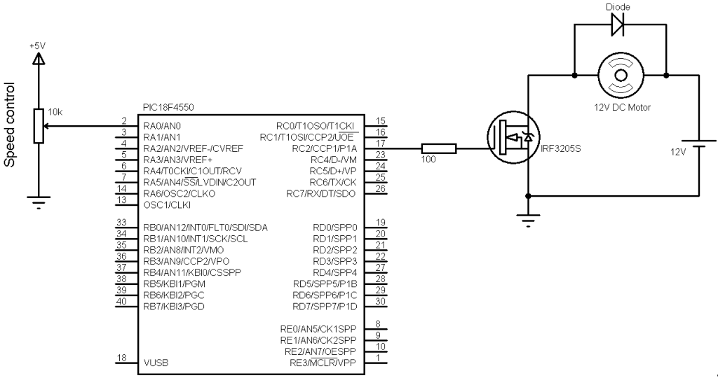
The nominal voltage of the DC motor is 12V.
The potentiometer used to control the speed of the motor, it is connected to AN0. The microcontroller reads the analog data from AN0 channel and uses the digital value (after conversion) to set the PWM duty cycle.
PIC18F4550 CCP1 module is used as PWM with a frequency of 500Hz.
PIC18F4550 microcontroller internal oscillator is used (8MHz) and MCLR pin function is disabled.
The PIC18F4550 microcontroller needs to be supplied with 5V between pins VDD (#11) and VSS (#12).
DC Motor speed control with PIC18F4550 CCS C code:
The code is described through its comments so there is no thing to add.
1 2 3 4 5 6 7 8 9 10 11 12 13 14 15 16 17 18 19 20 21 22 | // Dc motor speed control with PIC18F4550 CCS C code #include <18F4550.h> #device ADC = 10 #fuses NOMCLR INTRC_IO #use delay(clock = 8000000) unsigned int16 i ; void main(){ setup_oscillator(OSC_8MHZ); // Set internal oscillator to 8MHz setup_adc(ADC_CLOCK_DIV_8); // Set ADC conversion time to 8Tosc setup_adc_ports(AN0); // Configure AN0 as analog input set_adc_channel(0); // Select channel AN0 setup_ccp1(CCP_PWM); // Configure CCP1 as a PWM setup_timer_2(T2_DIV_BY_16, 250, 1); // Set PWM frequency to 500Hz delay_ms(100); // Wait 100ms while(TRUE){ i = read_adc(); // Read from AN0 and store in i set_pwm1_duty(i); // Set pwm1 duty cycle delay_ms(10); // Wait 10ms } } |
DC Motor speed control with PIC18F4550 video:
The following video shows a hardware circuit for this project with some details.


