In the previous post I’ve connected the DS18B20 temperature sensor with PIC18F4550 microcontroller in order to measure the ambient temperature, a 16×2 LCD was used to display the measured temperature. Now I’m going to add an SD card for storing the temperature values every 1 second. In this project DS3231 real time clock chip is used to keep time running even if the main power source is removed from the circuit, time and date are set using two pushbuttons connected to the PIC18F4550 microcontroller.
In the previous data logger projects I used SD cards (microSD) with FAT32 file system and in this project I’m going to test the FAT16 file system. Note that to be able to format a SD card with FAT16 file system, its size must be less than or equal to 2GB.
Related Projects:
Temperature and humidity data logger with PIC18F4550 and DHT22 sensor
PIC18F4550 with DS18B20 sensor and LCD project
DataLogger with PIC18F4550, SD card and DHT11 sensor
Read and write files from and to SD card with PIC18F4550 – CCS C
Real time clock & calendar with PIC18F4550 and DS3231 – CCS C
Hardware Required:
- PIC18F4550 microcontroller —> datasheet
- FAT16 formatted microSD card (size less than or equal to 2GB)
- DS3231 board with 3V coin cell battery —> DS3231 datasheet
- DS18B20 temperature sensor —> datasheet
- microSD card module
- USB-to-serial UART module (optional)
- 20×4 LCD screen
- 2 x pushbutton
- 8MHz crystal oscillator
- 2 x 22pF ceramic capacitors
- 4.7k ohm resistor
- 2 x 10k ohm resistor
- 10k ohm variable resistor or potentiometer
- Breadboard
- 5V source
- Jumper wires
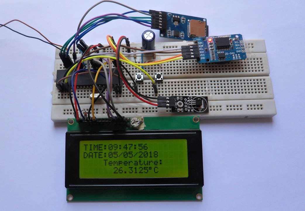
Temperature data logging with PIC18F4550 and DS18B20 circuit:
Project circuit schematic diagram is shown below.
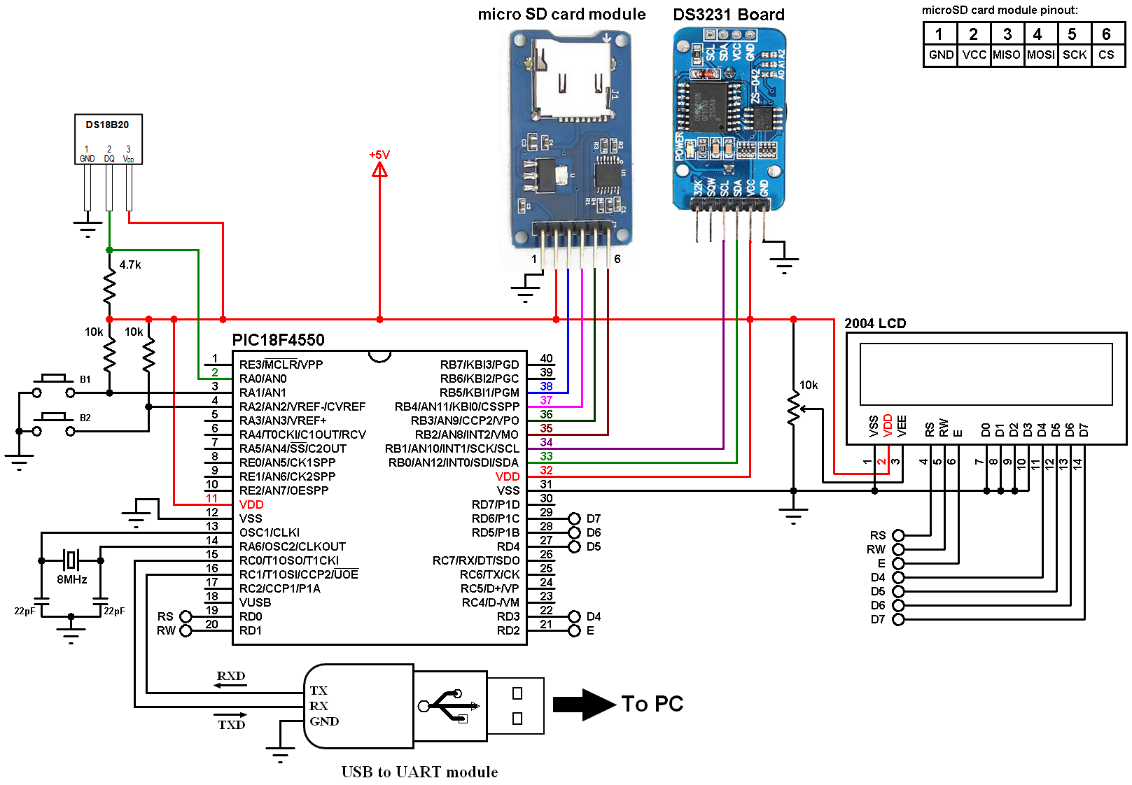
(All grounded terminals are connected together)
The DS18B20 sensor has 3 pins (from left to right): GND, data and VCC (+5V). The data pin is connected to PIC18F4550 pin RA0.
In the circuit there are two push buttons: B1 and B2 connected to pins RA1 and RA2 respectively, these buttons are used to set the time and the date of the real time clock. The real time clock chip used in this project is the DS3231, with the help of the 3V coin cell battery it allows the time to keep running even if the main power source is disconnected form the circuit.
The USB to serial UART module such as FT232RL is used to connect the microcontroller with the laptop (PC), in this example it shows the initialization status of the SD card and the FAT system.
In this project the microcontroller runs with an external crystal oscillator of 8MHz and MCLR pin is configured as a digital input pin (in the software).
As a hint, instead of the microSD card module we can use AMS1117-3V3 to supply the SD card and three voltage dividers for SS, SCK and MOSI lines; each voltage divider consists of two resistors: 2.2k ohm and 3.3k ohm. Related project link above shows the circuit diagram.
Temperature data logging with PIC18F4550 and DS18B20 C code:
The C code below is for CCS C compiler (PIC C), it was tested with version 5.051. The compilation of this C code may give some warnings, they can be ignored!
Before compiling the code we’ve to add MMC/SD card driver and FAT library for CCS C compiler, their download links are in the page below. The name of the two files (with the extension) respectively are: mmcsd_m.c and fat_m.c. After downloading just add the two files to the project folder or to CCS C drivers folder (for example C:\Program Files\CCS\Drivers):
SD Card driver and FAT Library for CCS C compiler
Or you can download them from the the 2 links below:
mmcsd_m.c download
fat_m.c download
With the 8MHz and PLL2 the microcontroller becomes working at 48MHZ (12 MIPS) which is the highest speed of the PIC18F4550.
In this project I used software SPI for the communication between the microcontroller and the SD card, and I used hardware I2C for the communication between the microcontroller and the DS3231.
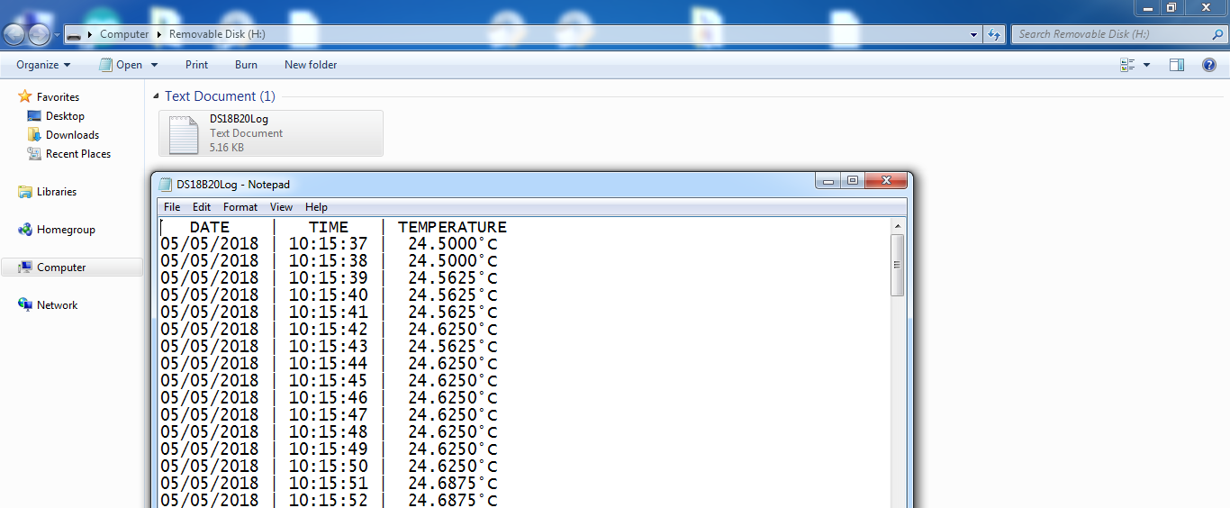
This code reads the temperature from the DS18B20 sensor and write its value as well as time and date to a file named “DS18B20Log.txt” (located in the SD card) every 1 second.
DS18B20 functions:
void ds18b20_start(): used to send start signal (reset) to the DS18B20 sensor.
void ds18b20_write_bit(int1 value): writes (sends) 1 bit to the DS18B20 sensor, the bit is ‘value’ which may be 1 or 0.
void ds18b20_write_byte(int8 value): writes 1 byte (8 bits) to the DS18B20 sensor, this function is based on the previous function. This function writes LSB (Least Significant Bit) first.
int1 ds18b20_read_bit(void): reads 1 bit from the DS18B20 sensor, returns the read value (1 or 0).
int8 ds18b20_read_byte(void): reads 1 byte (8 bits) from the DS18B20 sensor, this function is based on the previous function. This function reads LSB first, returns the read byte.
void ds18b20_start_conversion(): sends start conversion command to the sensor.
void ds18b20_read(int16 *raw_temp_value): reads the temperature raw data which is 16-bit long (two 8-bit registers), the data is stored in the variable raw_temp_value.
DS3231 functions:
void DS3231_display(): when called, this function displays the time and date on the 20×4 LCD screen.
void blink_parameter(): this function is responsible of making a parameter (hours, minutes, date, month or year) blinks while editing.
int8 set(x, y, parameter): with this function the setting of time and date is more easier where x and y are the position of the parameter on the LCD.
FAT library functions:
fat_init(): initializes the FAT system and the media card, returns 0 if every thing went OK and non-zero if there was an error.
mk_file: creates a new file on the SD card, returns 0 if OK, non-zero if error.
fatopen: opens a file, returns 0 if OK, non-zero if error.
fatputs: puts a string into the opened file, returns 0 if OK, non-zero if error.
fatclose: closes the opened file, after writing to the file we must call this function, returns 0 if OK, non-zero if there was an error.
Full CCS C code:
1 2 3 4 5 6 7 8 9 10 11 12 13 14 15 16 17 18 19 20 21 22 23 24 25 26 27 28 29 30 31 32 33 34 35 36 37 38 39 40 41 42 43 44 45 46 47 48 49 50 51 52 53 54 55 56 57 58 59 60 61 62 63 64 65 66 67 68 69 70 71 72 73 74 75 76 77 78 79 80 81 82 83 84 85 86 87 88 89 90 91 92 93 94 95 96 97 98 99 100 101 102 103 104 105 106 107 108 109 110 111 112 113 114 115 116 117 118 119 120 121 122 123 124 125 126 127 128 129 130 131 132 133 134 135 136 137 138 139 140 141 142 143 144 145 146 147 148 149 150 151 152 153 154 155 156 157 158 159 160 161 162 163 164 165 166 167 168 169 170 171 172 173 174 175 176 177 178 179 180 181 182 183 184 185 186 187 188 189 190 191 192 193 194 195 196 197 198 199 200 201 202 203 204 205 206 207 208 209 210 211 212 213 214 215 216 217 218 219 220 221 222 223 224 225 226 227 228 229 230 231 232 233 234 235 236 237 238 239 240 241 242 243 244 245 246 247 248 249 250 251 252 253 254 255 256 257 258 259 260 261 262 263 264 265 266 267 268 269 270 271 272 273 274 275 276 277 278 279 280 281 282 283 284 285 286 287 288 289 290 291 292 293 294 295 296 297 298 299 300 301 302 303 304 305 306 307 308 309 310 311 312 | /* Temperature logger with PIC18F4550 and DS18B20 C code for CCS C compiler http://simple-circuit.com/ */ // LCD module connections #define LCD_RS_PIN PIN_D0 #define LCD_RW_PIN PIN_D1 #define LCD_ENABLE_PIN PIN_D2 #define LCD_DATA4 PIN_D3 #define LCD_DATA5 PIN_D4 #define LCD_DATA6 PIN_D5 #define LCD_DATA7 PIN_D6 // End LCD module connections // SD card module connections #define MMCSD_PIN_SELECT PIN_B2 #define MMCSD_PIN_SCK PIN_B3 #define MMCSD_PIN_MOSI PIN_B4 #define MMCSD_PIN_MISO PIN_B5 // End SD card module connections #define FAT16 // Use FAT16 file system // DS18B20 sensor connection #define DS18B20_PIN PIN_A0 // DS18B20 Data pin is connected to pin RA0 // End DS18B20 sensor connection #define button1 PIN_A1 // Button B1 is connected to RA1 pin #define button2 PIN_A2 // Button B2 is connected to RA2 pin #include <18F4550.h> #device PASS_STRINGS = IN_RAM #fuses NOMCLR HSPLL PLL2 CPUDIV1 #use delay(clock = 48MHz) #use fast_io(A) #use fast_io(B) #use fast_io(D) #use I2C(MASTER, I2C1, FAST = 100000) // Initialize I2C #use rs232 (baud=9600, xmit=PIN_C0, rcv=PIN_C1) // Initialize UART protocol (needed for FAT library) #include <lcd.c> // Include LCD driver source file #include <mmcsd_m.c> // Include MMC/SD card driver source file #include <fat_m.c> // Include FAT library source file // DS18B20 variables int16 raw_temp; char *temp = "000.0000 C"; // Time and calendar variables char Time[] = " : : "; char Calendar[] = " / /20 "; int8 i, second, minute, hour, date, month, year, previous_second ; // FAT file system variable int8 fat_status; FILE LogFile; //////////// DS18B20 functions //////////// void ds18b20_start(){ output_low(DS18B20_PIN); // Send reset pulse to the DS18B20 sensor output_drive(DS18B20_PIN); // Configure DS18B20_PIN pin as output delay_us(500); // Wait 500 us output_float(DS18B20_PIN); // Configure DS18B20_PIN pin as input delay_us(500); //wait to read the DS18B20 sensor response } void ds18b20_write_bit(int1 value){ output_low(DS18B20_PIN); output_drive(DS18B20_PIN); // Configure DS18B20_PIN pin as output delay_us(2); // Wait 2 us output_bit(DS18B20_PIN, value); delay_us(80); // Wait 80 us output_float(DS18B20_PIN); // Configure DS18B20_PIN pin as input delay_us(2); // Wait 2 us } void ds18b20_write_byte(int8 value){ int8 i; for(i = 0; i < 8; i++) ds18b20_write_bit(bit_test(value, i)); } int1 ds18b20_read_bit(void) { int1 value; output_low(DS18B20_PIN); output_drive(DS18B20_PIN); // Configure DS18B20_PIN pin as output delay_us(2); output_float(DS18B20_PIN); // Configure DS18B20_PIN pin as input delay_us(5); // Wait 5 us value = input(DS18B20_PIN); delay_us(100); // Wait 100 us return value; } int8 ds18b20_read_byte(void) { int8 i, value = 0; for(i = 0; i < 8; i++) shift_right(&value, 1, ds18b20_read_bit()); return value; } void ds18b20_start_conversion() { ds18b20_start(); // Send start pulse ds18b20_write_byte(0xCC); // Send skip ROM command ds18b20_write_byte(0x44); // Send start conversion command } void ds18b20_read(int16 *raw_temp_value) { ds18b20_start(); // Send start pulse ds18b20_write_byte(0xCC); // Send skip ROM command ds18b20_write_byte(0xBE); // Send read command *raw_temp_value = ds18b20_read_byte(); // Read temperature LSB byte and store it on raw_temp_value LSB byte *raw_temp_value |= (int16)(ds18b20_read_byte()) << 8; // Read temperature MSB byte and store it on raw_temp_value MSB byte } //////////// DS3231 functions //////////// void DS3231_display(){ // Convert BCD to decimal second = (second >> 4) * 10 + (second & 0x0F); minute = (minute >> 4) * 10 + (minute & 0x0F); hour = (hour >> 4) * 10 + (hour & 0x0F); date = (date >> 4) * 10 + (date & 0x0F); month = (month >> 4) * 10 + (month & 0x0F); year = (year >> 4) * 10 + (year & 0x0F); // End conversion Time[7] = second % 10 + 48; Time[6] = second / 10 + 48; Time[4] = minute % 10 + 48; Time[3] = minute / 10 + 48; Time[1] = hour % 10 + 48; Time[0] = hour / 10 + 48; Calendar[9] = year % 10 + 48; Calendar[8] = year / 10 + 48; Calendar[4] = month % 10 + 48; Calendar[3] = month / 10 + 48; Calendar[1] = date % 10 + 48; Calendar[0] = date / 10 + 48; lcd_gotoxy(6, 1); printf(lcd_putc, Time); // Display time lcd_gotoxy(6, 2); printf(lcd_putc, Calendar); // Display calendar } void blink_parameter(){ int8 j = 0; while(j < 10 && input(button1) && input(button2)){ j++; delay_ms(25); } } int8 set(x, y, parameter){ while(!input(button1)); // Wait until button (pin #8) released while(TRUE){ while(!input(button2)){ // If button (pin #9) is pressed parameter++; if(i == 0 && parameter > 23) // If hours > 23 ==> hours = 0 parameter = 0; if(i == 1 && parameter > 59) // If minutes > 59 ==> minutes = 0 parameter = 0; if(i == 2 && parameter > 31) // If date > 31 ==> date = 1 parameter = 1; if(i == 3 && parameter > 12) // If month > 12 ==> month = 1 parameter = 1; if(i == 4 && parameter > 99) // If year > 99 ==> year = 0 parameter = 0; lcd_gotoxy(x, y); printf(lcd_putc,"%02u", parameter); // Display parameter delay_ms(200); // Wait 200ms } lcd_gotoxy(x, y); lcd_putc(" "); blink_parameter(); lcd_gotoxy(x, y); // Display two spaces printf(lcd_putc,"%02u", parameter); // Display parameter blink_parameter(); if(!input(button1)){ // If button (pin #8) is pressed i++; // Increament 'i' for the next parameter return parameter; // Return parameter value and exit } } } void main(void) { lcd_init(); // Initialize LCD module lcd_putc('\f'); // clear LCD command lcd_gotoxy(1, 1); lcd_putc("TIME:"); lcd_gotoxy(1, 2); lcd_putc("DATE:"); lcd_gotoxy(25, 1); lcd_putc("Temperature:"); ds18b20_start_conversion(); delay_ms(1000); // wait 2 seconds // Initializing the FAT library as well as the SD card ---> returns 0 if OK printf("Initializing FAT library ... "); fat_status = fat_init(); if( fat_status == 0 ) { // initialization OK printf("OK"); mk_file("/DS18B20Log.txt"); // Create a new file with name 'DS18B20Log.txt' fatopen("/DS18B20Log.txt", "a", &LogFile); // Open 'DS18B20Log.txt' with write append 'a' fatputs(" DATE | TIME | TEMPERATURE\r\n", &LogFile); fatclose(&LogFile); } else // FAT initialization error printf("Error!"); while(TRUE) { if(!input(button1)){ // If button1 is pressed i = 0; hour = set(6, 1, hour); minute = set(9, 1, minute); date = set(6, 2, date); month = set(9, 2, month); year = set(14, 2, year); // Convert decimal to BCD minute = ((minute / 10) << 4) + (minute % 10); hour = ((hour / 10) << 4) + (hour % 10); date = ((date / 10) << 4) + (date % 10); month = ((month / 10) << 4) + (month % 10); year = ((year / 10) << 4) + (year % 10); // End conversion // Write data to DS3231 RTC i2c_start(); // Start I2C i2c_write(0xD0); // DS3231 address i2c_write(0); i2c_write(0); // Reset sesonds and start oscillator i2c_write(minute); // Write minute value to DS3231 i2c_write(hour); // Write hour value to DS3231 i2c_write(1); // Write day value (not used) i2c_write(date); // Write date value to DS3231 i2c_write(month); // Write month value to DS3231 i2c_write(year); // Write year value to DS3231 i2c_stop(); // Stop I2C delay_ms(200); // Wait 200ms } // end if(!input(button1)) // Read data from the DS3231 i2c_start(); // Start I2C i2c_write(0xD0); // DS3231 address i2c_write(0); // Send register address i2c_start(); // Restart I2C i2c_write(0xD1); // Initialize data read second = i2c_read(1); // Read seconds from register 0 minute = i2c_read(1); // Read minuts from register 1 hour = i2c_read(1); // Read hour from register 2 i2c_read(1); // Read day from register 3 (not used) date = i2c_read(1); // Read date from register 4 month = i2c_read(1); // Read month from register 5 year = i2c_read(0); // Read year from register 6 i2c_stop(); // Stop I2C DS3231_display(); // Diaplay time & calendar on the LCD screen if( second != previous_second ) { previous_second = second; // Read temperature from DS18B20 sensor ds18b20_read(&raw_temp); if(raw_temp & 0x8000) { // If the temperature is negative temp[0] = '-'; // Put minus sign (-) raw_temp = ~raw_temp + 1; // Change temperature value to positive form } else { if((raw_temp >> 4) >= 100) // If the temperatue >= 100 °C temp[0] = '1'; // Put 1 of hundreds else // otherwise temp[0] = ' '; // put space ' ' } // Put the first two digits ( for tens and ones) temp[1] = ( (raw_temp >> 4) / 10 ) % 10 + 48; // Put tens digit temp[2] = (raw_temp >> 4) % 10 + 48; // Put ones digit // Put the 4 fraction digits (digits after the point) // Why 625: because we're working with 12-bit resolution (default resolution) temp[4] = ( (raw_temp & 0x0F) * 625) / 1000 + 48; // Put thousands digit temp[5] = (((raw_temp & 0x0F) * 625) / 100 ) % 10 + 48; // Put hundreds digit temp[6] = (((raw_temp & 0x0F) * 625) / 10 ) % 10 + 48; // Put tens digit temp[7] = ( (raw_temp & 0x0F) * 625) % 10 + 48; // Put ones digit temp[8] = 223; // Put degree symbol ( ° ) for the LCD lcd_gotoxy(26, 2); // Go to column 4 row 2 printf(lcd_putc, temp); if( fat_status == 0 ) { temp[8] = '°'; // Put degree symbol (°) for 'Log.txt' file fatopen("/DS18B20Log.txt", "a", &LogFile); // Open 'DS18B20Log.txt' with append permission 'a' fatputs(Calendar, &LogFile); fatputs(" | ", &LogFile); fatputs(Time, &LogFile); fatputs(" | ", &LogFile); fatputs(temp, &LogFile); fatputs("\r\n", &LogFile); fatclose(&LogFile); } // end if( fat_status == 0 ) ds18b20_start_conversion(); } // end if( second != previous_second ) delay_ms(50); } // end while(TRUE) } // end void main() // End of code |
The video below shows the simulation of the project with Proteus ISIS, I got the same result as the real hardware circuit. Note that the simulation circuit is not the same as the hardware circuit, the hardware circuit diagram is shown above.
In my hardware circuit I used Samsung 2GB microSD card and the result is shown below where the “DS18B20Log.txt” file is clearly shown:
Downloads:
Proteus simulation file download:
Download
SD card image file (FAT16_SD) download:
Download


hello sir
what crystal in project is 8MHz but in source code is 48MHz?
its false this project, because not work the code and where is it “fat16_sd.exe” ??
can you give the hex file?
Can you please give the .hex files.
I am a beginner.