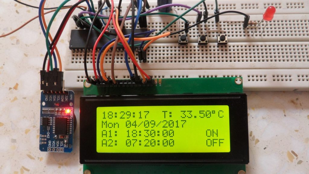
After the simple interfacing of the PIC18F4550 microcontroller with the DS3231 RTC, now let’s add the alarms functionality and temperature monitor to our previous project.
Interfacing PIC18F4550 with DS3231 project link:
Real time clock & calendar with PIC18F4550 and DS3231
As written in the datasheet the DS3231 RTC has a built-in 2 alarm functions and a digital temperature sensor with an accuracy of ±3°C.
Hardware Required:
- PIC18F4550 microcontroller
- 20×4 LCD screen
- 10K ohm variable resistor
- 330 ohm resistor
- LED
- 3 x push button
- 5V supply source
- Breadboard
- Jumper wires
DS3231 board contains the following components:
- DS3231 RTC – datasheet
- 3 x 4.7K ohm resistors
- 0.1uF ceramic capacitor
- 3V coin cell battery
The circuit:
Project circuit diagram is shown below.
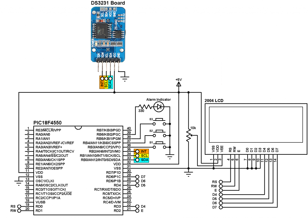
To simplify the circuit, I used the DS3231 board, this board basically contains the main chip which is the DS3231, pull-up resistors (4.7K) of SCL, SDA and INT/SQW lines and coin cell battery holder. There is also 24C32 EEPROM and some other resistors (not used in this project).
The DS3231 board is supplied with 5V as the microcontroller and the 2004 LCD, there are 3 data lined connected between this board and the PIC18F4550 MCU, SCL line is connected to pin RB1, SDA is connected to pin RB0 and INT line is connected to pin RB2 which is the external interrupt 2 pin of the PIC18F4550 MCU. The DS3231 interrupts the microcontroller when there is an alarm.
In the circuit there are 3 push buttons: B1, B2 and B3. These buttons are used to set time, calendar and alarms. Time and calendar can be adjusted with B1 and B2, button B1 selects time or date parameter (time parameters: hours and minutes; calendar parameters: day, date, month and year) and B2 increments the selected parameter. The button B3 and B2 adjust alarm1 and alarm2 parameters (hours, minutes and ON/OFF), button B3 selects the parameter and B2 increments the selected parameter.
There is an LED connected to pin RB6, this LED is used as an alarm indicator (alarm1 or alarm2), so if there is an alarm the DS3231 pulls down the INT pin which interrupts the microcontroller and the microcontroller turns the LED ON, here button B2 turns both the LED and the occurred alarm OFF.
In this project the PIC18F4550 MCU uses its internal oscillator and MCLR pin function is disabled.
CCS C code:
The C code below was tested with CCS C compiler version 5.051.
By reading the datasheet of the DS3231 RTC the code will be more easier!
The hardware I2C module of the MCU is initialized and configured using the following CCS C function with a speed of 100KHz:
#use I2C(master, I2C1, FAST = 100000)
master: set the microcontroller to the master mode
I2C1: use first I2C module.
The DS3231 works with BCD format only (except temperature) and to convert the BCD to decimal and vise versa I used the following functions (example for minute variable):
minute = (minute >> 4) * 10 + (minute & 0x0F); // Convert BCD to decimal
minute = ((minute / 10) << 4) + (minute % 10); // Convert decimal to BCD
Code functions:
void DS3231_read() : this function reads time and calendar data from the DS3231 (seconds, minutes, hours, day, date, month and year).
void DS3231_display() : displays time and calendar data, before displaying time and calendar data are converted from BCD format to decimal format. This function displays the calendar by calling a function named void calendar_display() .
void alarms_read_display() : basically this functions reads alarm1 and alarm2 minutes and hours. It also reads the DS3231 control register, status register and 2 temperature registers.
The other job of this function is to display alarms data (hours, minutes and status) and the temperature value. The alarm status are extracted from the control register.
int8 edit(parameter, x, y) : I used this function to edit time, calendar and alarm parameters except the day. I used a variable named i to distinguish between the parameters:
i = 0, 1 : time hours and minutes respectively
i = 2, 3, 4: date month, year respectively
i = 5, 6: alarms hours and minutes respectively
i = 7: alarms status (ON or OFF)
After the edit of time/calendar/alarms the data have to be converted back to BCD format and written to the DS3231.
The MCU turns the LED ON when it interrupted by the DS3231, the DS3231 sends the interrupt signal (pulls down the INT line) when there has been an alarm. Button B2 resets and turns OFF the alarm. If both alarms are active, button B2 will resets and turns OFF the occurred alarm only and keeps the other as it is. To do that we’ve to detect which alarm was occurred which can be easily done by reading the status register of the DS3231 (A1IF and A2IF flag bits). Turning ON or OFF an alarm is done by writing to the control register (bits: INTCN, A1IE and A2IE). Always INTCN bit should be 1. I used the following line to write 1 to the INTCN bit and to turn OFF the occurred alarm:
i2c_write(4 | (!bit_test(status_reg, 0) & alarm1_status) | ((!bit_test(status_reg, 1) & alarm2_status) << 1));
alarm1_status and alarm2_status are 1-bit variables, for example if alarm1_status is 1 ==> alarm1 is ON and if alarm1_status is 0 ==> alarm1 is OFF. The same thing for alarm2.
The complete C code is below.
1 2 3 4 5 6 7 8 9 10 11 12 13 14 15 16 17 18 19 20 21 22 23 24 25 26 27 28 29 30 31 32 33 34 35 36 37 38 39 40 41 42 43 44 45 46 47 48 49 50 51 52 53 54 55 56 57 58 59 60 61 62 63 64 65 66 67 68 69 70 71 72 73 74 75 76 77 78 79 80 81 82 83 84 85 86 87 88 89 90 91 92 93 94 95 96 97 98 99 100 101 102 103 104 105 106 107 108 109 110 111 112 113 114 115 116 117 118 119 120 121 122 123 124 125 126 127 128 129 130 131 132 133 134 135 136 137 138 139 140 141 142 143 144 145 146 147 148 149 150 151 152 153 154 155 156 157 158 159 160 161 162 163 164 165 166 167 168 169 170 171 172 173 174 175 176 177 178 179 180 181 182 183 184 185 186 187 188 189 190 191 192 193 194 195 196 197 198 199 200 201 202 203 204 205 206 207 208 209 210 211 212 213 214 215 216 217 218 219 220 221 222 223 224 225 226 227 228 229 230 231 232 233 234 235 236 237 238 239 240 241 242 243 244 245 246 247 248 249 250 251 252 253 254 255 256 257 258 259 260 261 262 263 264 265 266 267 268 269 270 271 272 273 274 275 276 277 278 279 280 281 282 283 284 285 286 287 288 289 290 291 292 293 294 295 296 297 298 299 300 301 302 303 304 305 306 307 308 309 310 311 312 313 314 315 316 317 318 319 320 321 322 323 324 325 326 327 328 329 330 | /* Real time clock and calendar with 2 alarms and temperature sensing using PIC18F4550 MCU & DS3231 CCS C code. Read DS3231 RTC datasheet to understand the code! Time & date parameters can be set using two push buttons connected to pins RB3 & RB4. Alarm1 and alarm2 can be set using buttons connected to pins RB5 and RB4. Pin RB6 becomes high when an alarm occurred and button RB4 returns it to low and turns the occurred alarm OFF. DS3231 interrupt pin is connected to PIC18F4550 external interrupt 2 pin (RB2). */ // LCD module connections #define LCD_RS_PIN PIN_D0 #define LCD_RW_PIN PIN_D1 #define LCD_ENABLE_PIN PIN_D2 #define LCD_DATA4 PIN_D3 #define LCD_DATA5 PIN_D4 #define LCD_DATA6 PIN_D5 #define LCD_DATA7 PIN_D6 // End LCD module connections #include <18F4550.h> #fuses NOMCLR, INTRC_IO, NOWDT,NOPROTECT,NOLVP #use delay(clock = 8000000) #include <lcd.c> #use fast_io(B) #use fast_io(D) #use I2C(master, I2C1, FAST = 100000) int1 alarm1_status, alarm2_status; char time[] = " : : ", calendar[] = " / /20 ", alarm1[] = "A1: : :00", alarm2[] = "A2: : :00", temperature[] = "T: . C"; int8 i, second, minute, hour, day, date, month, year, alarm1_minute, alarm1_hour, alarm2_minute, alarm2_hour, status_reg; #INT_EXT2 // External interrupt routine void ext2_isr(void){ output_high(PIN_B6); clear_interrupt(INT_EXT2); } void DS3231_read(){ // Read time & calendar data function i2c_start(); // Start I2C protocol i2c_write(0xD0); // DS3231 address i2c_write(0); // Send register address (seconds register) i2c_start(); // Restart I2C i2c_write(0xD1); // Initialize data read second = i2c_read(1); // Read seconds from register 0 minute = i2c_read(1); // Read minutes from register 1 hour = i2c_read(1); // Read hour from register 2 day = i2c_read(1); // Read day from register 3 date = i2c_read(1); // Read date from register 4 month = i2c_read(1); // Read month from register 5 year = i2c_read(0); // Read year from register 6 i2c_stop(); // Stop I2C protocol } void alarms_read_display(){ // Read and display alarm1 and alarm2 data function int8 control_reg, temperature_lsb; signed int8 temperature_msb; i2c_start(); // Start I2C protocol i2c_write(0xD0); // DS3231 address i2c_write(0x08); // Send register address (alarm1 minutes register) i2c_start(); // Restart I2C i2c_write(0xD1); // Initialize data read alarm1_minute = i2c_read(1); // Read alarm1 minutes alarm1_hour = i2c_read(1); // Read alarm1 hours i2c_read(1); // Skip alarm1 day/date register alarm2_minute = i2c_read(1); // Read alarm2 minutes alarm2_hour = i2c_read(1); // Read alarm2 hours i2c_read(1); // Skip alarm2 day/date register control_reg = i2c_read(1); // Read the DS3231 control register status_reg = i2c_read(1); // Read the DS3231 status register i2c_read(1); // Skip aging offset register temperature_msb = i2c_read(1); // Read temperature MSB temperature_lsb = i2c_read(0); // Read temperature LSB i2c_stop(); // Stop I2C protocol // Convert BCD to decimal alarm1_minute = (alarm1_minute >> 4) * 10 + (alarm1_minute & 0x0F); alarm1_hour = (alarm1_hour >> 4) * 10 + (alarm1_hour & 0x0F); alarm2_minute = (alarm2_minute >> 4) * 10 + (alarm2_minute & 0x0F); alarm2_hour = (alarm2_hour >> 4) * 10 + (alarm2_hour & 0x0F); // End conversion alarm1[8] = alarm1_minute % 10 + 48; alarm1[7] = alarm1_minute / 10 + 48; alarm1[5] = alarm1_hour % 10 + 48; alarm1[4] = alarm1_hour / 10 + 48; alarm2[8] = alarm2_minute % 10 + 48; alarm2[7] = alarm2_minute / 10 + 48; alarm2[5] = alarm2_hour % 10 + 48; alarm2[4] = alarm2_hour / 10 + 48; alarm1_status = bit_test(control_reg, 0); // Read alarm1 interrupt enable bit (A1IE) from DS3231 control register alarm2_status = bit_test(control_reg, 1); // Read alarm2 interrupt enable bit (A2IE) from DS3231 control register if(temperature_msb < 0){ temperature_msb = abs(temperature_msb); temperature[2] = '-'; } else temperature[2] = ' '; if(temperature_msb > 99) temperature[2] = '1'; temperature_lsb >>= 6; temperature[4] = temperature_msb % 10 + 48; temperature[3] = (temperature_msb / 10) % 10 + 48; if(temperature_lsb == 0 || temperature_lsb == 2){ temperature[7] = '0'; if(temperature_lsb == 0) temperature[6] = '0'; else temperature[6] = '5'; } if(temperature_lsb == 1 || temperature_lsb == 3){ temperature[7] = '5'; if(temperature_lsb == 1) temperature[6] = '2'; else temperature[6] = '7'; } temperature[8] = 223; // Degree symbol lcd_gotoxy(11, 1); // Go to column 10 row 1 printf(lcd_putc, temperature); // Display temperature lcd_gotoxy(21, 1); // Go to column 1 row 3 printf(lcd_putc, alarm1); // Display alarm1 lcd_gotoxy(38, 1); // Go to column 18 row 3 if(alarm1_status) lcd_putc("ON "); // If A1IE = 1 print 'ON' else lcd_putc("OFF"); // If A1IE = 0 print 'OFF' lcd_gotoxy(21, 2); // Go to column 1 row 4 printf(lcd_putc, alarm2); // Display alarm2 lcd_gotoxy(38, 2); // Go to column 18 row 4 if(alarm2_status) lcd_putc("ON "); // If A2IE = 1 print 'ON' else lcd_putc("OFF"); // If A2IE = 0 print 'OFF' } void calendar_display(){ // Display calendar function switch(day){ case 1: strcpy(calendar, "Sun / /20 "); break; case 2: strcpy(calendar, "Mon / /20 "); break; case 3: strcpy(calendar, "Tue / /20 "); break; case 4: strcpy(calendar, "Wed / /20 "); break; case 5: strcpy(calendar, "Thu / /20 "); break; case 6: strcpy(calendar, "Fri / /20 "); break; case 7: strcpy(calendar, "Sat / /20 "); break; default: strcpy(calendar, "Sat / /20 "); break; } calendar[13] = year % 10 + 48; calendar[12] = year / 10 + 48; calendar[8] = month % 10 + 48; calendar[7] = month / 10 + 48; calendar[5] = date % 10 + 48; calendar[4] = date / 10 + 48; lcd_gotoxy(1, 2); // Go to column 1 row 2 printf(lcd_putc, calendar); // Display calendar } void DS3231_display(){ // Convert BCD to decimal second = (second >> 4) * 10 + (second & 0x0F); minute = (minute >> 4) * 10 + (minute & 0x0F); hour = (hour >> 4) * 10 + (hour & 0x0F); date = (date >> 4) * 10 + (date & 0x0F); month = (month >> 4) * 10 + (month & 0x0F); year = (year >> 4) * 10 + (year & 0x0F); // End conversion time[7] = second % 10 + 48; time[6] = second / 10 + 48; time[4] = minute % 10 + 48; time[3] = minute / 10 + 48; time[1] = hour % 10 + 48; time[0] = hour / 10 + 48; calendar_display(); // Call calendar display function lcd_gotoxy(1, 1); // Go to column 1 row 1 printf(lcd_putc, time); // Display time } void blink(){ int8 j = 0; while(j < 10 && (input(PIN_B3) || i >= 5) && input(PIN_B4) && (input(PIN_B5) || i < 5)){ j++; delay_ms(25); } } int8 edit(parameter, x, y){ while(!input(PIN_B3) || !input(PIN_B5)); // Wait until button RB0 is released while(TRUE){ while(!input(PIN_B4)){ // If button RB2 is pressed parameter++; if(((i == 0) || (i == 5)) && parameter > 23) // If hours > 23 ==> hours = 0 parameter = 0; if(((i == 1) || (i == 6)) && parameter > 59) // If minutes > 59 ==> minutes = 0 parameter = 0; if(i == 2 && parameter > 31) // If date > 31 ==> date = 1 parameter = 1; if(i == 3 && parameter > 12) // If month > 12 ==> month = 1 parameter = 1; if(i == 4 && parameter > 99) // If year > 99 ==> year = 0 parameter = 0; if(i == 7 && parameter > 1) // For alarms ON or OFF (1: alarm ON, 0: alarm OFF) parameter = 0; lcd_gotoxy(x, y); if(i == 7){ // For alarms ON & OFF if(parameter == 1) lcd_putc("ON "); else lcd_putc("OFF"); } else printf(lcd_putc,"%02u", parameter); // Display parameter if(i >= 5){ DS3231_read(); // Read data from DS3231 DS3231_display(); // Display DS3231 time and calendar } delay_ms(200); // Wait 200ms } lcd_gotoxy(x, y); // Go to LCD x column and y row lcd_putc(" "); // Print two spaces if(i == 7) lcd_putc(" "); // Print space (for alarms ON & OFF) blink(); // Call blink function lcd_gotoxy(x, y); // Go to LCD x column and y row if(i == 7){ // For alarms ON & OFF if(parameter == 1) lcd_putc("ON "); else lcd_putc("OFF"); } else printf(lcd_putc,"%02u", parameter); // Display parameter blink(); if(i >= 5){ DS3231_read(); DS3231_display();} if((!input(PIN_B3) && i < 5) || (!input(PIN_B5) && i >= 5)){ i++; // Increment 'i' for the next parameter return parameter; // Return parameter value and exit } } } void main(){ setup_oscillator(OSC_8MHZ); // Set internal oscillator to 8MHz output_low(PIN_B6); output_drive(PIN_B6); // Configure pin RB6 as output set_tris_d(0); // Configure PORTD pins as outputs port_b_pullups(TRUE); // Enable PORTB internal pull-ups enable_interrupts(GLOBAL); // Enable global interrupts enable_interrupts(INT_EXT2_H2L); // Enable external interrupt with edge from high to low lcd_init(); // Initialize LCD module lcd_putc('\f'); // LCD clear while(TRUE){ if(!input(PIN_B3)){ // If RB1 button is pressed i = 0; hour = edit(hour, 1, 1); minute = edit(minute, 4, 1); while(!input(PIN_B3)); // Wait until button RB0 released while(TRUE){ while(!input(PIN_B4)){ // If button RB2 button is pressed day++; // Increment day if(day > 7) day = 1; calendar_display(); // Call display calendar lcd_gotoxy(1, 2); // Go to column 1 row 2 printf(lcd_putc, calendar); // Display calendar delay_ms(200); } lcd_gotoxy(1, 2); // Go to column 1 row 2 lcd_putc(" "); // Print 3 spaces blink(); lcd_gotoxy(1, 2); // Go to column 1 row 2 printf(lcd_putc, calendar); // Print calendar blink(); // Call blink function if(!input(PIN_B3)) // If button RB1 is pressed break; } date = edit(date, 5, 2); // Edit date month = edit(month, 8, 2); // Edit month year = edit(year, 13, 2); // Edit year // Convert decimal to BCD minute = ((minute / 10) << 4) + (minute % 10); hour = ((hour / 10) << 4) + (hour % 10); date = ((date / 10) << 4) + (date % 10); month = ((month / 10) << 4) + (month % 10); year = ((year / 10) << 4) + (year % 10); // End conversion // Write time & calendar data to DS3231 RTC i2c_start(); // Start I2C protocol i2c_write(0xD0); // DS3231 address i2c_write(0); // Send register address (seconds address) i2c_write(0); // Reset seconds and start oscillator i2c_write(minute); // Write minute value to DS3231 i2c_write(hour); // Write hour value to DS3231 i2c_write(day); // Write day value i2c_write(date); // Write date value to DS3231 i2c_write(month); // Write month value to DS3231 i2c_write(year); // Write year value to DS3231 i2c_stop(); // Stop I2C delay_ms(200); // Wait 200ms } if(!input(PIN_B5)){ // If RB3 button is pressed while(!input(PIN_B5)); // Wait until button RB3 released i = 5; alarm1_hour = edit(alarm1_hour, 25, 1); alarm1_minute = edit(alarm1_minute, 28, 1); alarm1_status = edit(alarm1_status, 38, 1); i = 5; alarm2_hour = edit(alarm2_hour, 25, 2); alarm2_minute = edit(alarm2_minute, 28, 2); alarm2_status = edit(alarm2_status, 38, 2); alarm1_minute = ((alarm1_minute / 10) << 4) + (alarm1_minute % 10); alarm1_hour = ((alarm1_hour / 10) << 4) + (alarm1_hour % 10); alarm2_minute = ((alarm2_minute / 10) << 4) + (alarm2_minute % 10); alarm2_hour = ((alarm2_hour / 10) << 4) + (alarm2_hour % 10); // Write alarms data to DS3231 i2c_start(); // Start I2C i2c_write(0xD0); // DS3231 address i2c_write(7); // Send register address (alarm1 seconds) i2c_write(0); // Write 0 to alarm1 seconds i2c_write(alarm1_minute); // Write alarm1 minutes value to DS3231 i2c_write(alarm1_hour); // Write alarm1 hours value to DS3231 i2c_write(0x80); // Alarm1 when hours, minutes, and seconds match i2c_write(alarm2_minute); // Write alarm2 minutes value to DS3231 i2c_write(alarm2_hour); // Write alarm2 hours value to DS3231 i2c_write(0x80); // Alarm2 when hours and minutes match i2c_write(4 | alarm1_status | (alarm2_status << 1)); // Write data to DS3231 control register (enable interrupt when alarm) i2c_write(0); // Clear alarm flag bits i2c_stop(); // Stop I2C delay_ms(200); // Wait 200ms } if(!input(PIN_B4) && input(PIN_B6)){ // When button B2 pressed with alarm (Reset and turn OFF the alarm) output_low(PIN_B6); // Turn OFF the alarm indicator i2c_start(); // Start I2C i2c_write(0xD0); // DS3231 address i2c_write(0x0E); // Send register address (control register) // Write data to control register (Turn OFF the occurred alarm and keep the other as it is) i2c_write(4 | (!bit_test(status_reg, 0) & alarm1_status) | ((!bit_test(status_reg, 1) & alarm2_status) << 1)); i2c_write(0); // Clear alarm flag bits i2c_stop(); // Stop I2C } DS3231_read(); // Read time and calendar parameters from DS3231 RTC alarms_read_display(); // Read and display alarms parameters DS3231_display(); // Display time & calendar delay_ms(50); // Wait 50ms } } // End of code |
Video:
After connecting the circuit and burning the HEX file into the MCU, I got the result shown similar to what’s in the video below where the used microcontroller is PIC16F877A.


