This post shows how to control a 5V DC motor speed and direction of rotation using ESP8266 NodeMCU development board and L293D motor driver chip.
The speed and rotation direction of the DC motor is controlled from a rotary encoder connected to the NodeMCU board.
In this project I used the rotary encoder shown below:
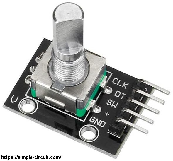
This rotary encoder has 5 pins: GND, + (+5V or 3.3V), SW (push button), DT (pin B) and CLK (pin A).
As an addition to the rotary encoder there is a push button and three a pull up resistors for pins SW, DT and CLK of 10k ohm. With the three pull-up resistors, the normal state of each terminal is logic high.
The rotary encoder generates (when rotating) two square waves on pins A (CLK) and B (DT) with 90° out of phase as shown in the figure below:
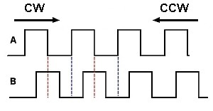
Since the normal state of pin A (CLK) and pin B (DT) are logic high we’ve to detect falling (transition from high to low) of one of them, here pin A is used to detect the movement of the rotary encoder in both directions (falling of pin A signal). Direction of rotation can be detected by knowing the status of pin B, if pin B is logic high this means the direction of rotation is clockwise (CW), and if pin B is logic low this means the direction of rotation is counter clockwise (CCW).
Hardware Required:
- ESP8266 NodeMCU development board
- Rotary encoder
- 5V DC motor
- L293D motor driver
- Breadboard
- 5V source
- Jumper wires
ESP8266 NodeMCU DC motor control circuit:
Project circuit schematic diagram is shown below.
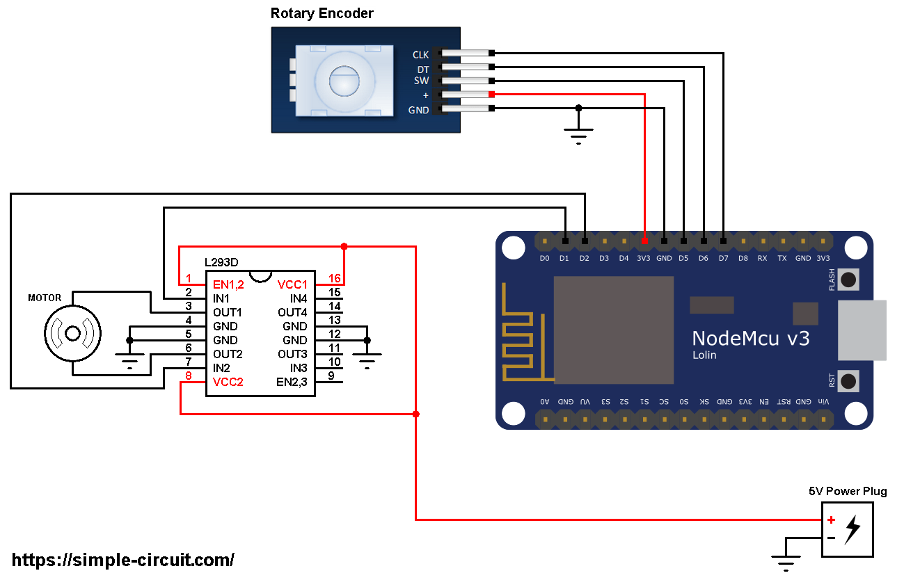
All the grounded terminals are connected together (don’t forget the external 5V source negative terminal).
As shown in the circuit diagram there is an external power source of 5V (5V Power Plug). This source is used to fed the DC motor with sufficient power because the NodeMCU board may not be able to do that.
The L293D quadruple half-H drivers chip allows us to drive 2 motors in both directions. With two PWM outputs from the NodeMCU board we can easily control the speed as well as the rotation direction of one DC motor. (PWM: Pulse Width Modulation).
The L293D is supplied with 5V that comes from the external power source (pins: VCC1, VCC2 and EN1,2).
Pin IN1 and pin IN2 are the control pins where:
| IN1 | IN2 | Function |
| L | H | Direction 1 |
| H | L | Direction 2 |
| L | L | Fast motor stop |
| H | H | Fast motor stop |
Pins IN1 and IN2 of the L293D are respectively connected to NodeMCU pins D1 and D2. These pin (D1 & D2) are PWM signal outputs, at any time there is only 1 active PWM, this allows us to control the direction and the speed of the DC motor by varying the duty cycle of the active PWM signal. The active PWM pin decides motor direction of rotation (one at a time, the other output is logic 0).
The rotary encoder has 5 pins, they’re connected to the NodeMCU board as follows:
GND pin of the rotary encoder is connected to NodeMCU GND pin,
+ pin is connected to 3V3 PIN,
SW pin is connected to pin D5,
DT pin is connected to pin D6,
CLK pin is connected to pin D7.
ESP8266 NodeMCU DC motor control Arduino code:
Input pins (connected to the rotary encoder) and output pins (connected to the L293D) are defined in the Arduino code as shown below:
1 2 3 4 5 | #define SW D5 // Rotary encoder push-button pin (SW) is connected to Arduino pin 4 #define DT D6 // DT pin #define CLK D7 // CLK pin #define PWM1 D1 // PWM1 output #define PWM2 D2 // PWM2 output |
When rotated, the rotary encoder generates a series of pulses on pins DT and CLK which interrupt the NodeMCU microcontroller (ESP8266EX). The two interrupts are initialized with the following lines:
1 2 | attachInterrupt(DT, enc_read, CHANGE); attachInterrupt(CLK, enc_read, CHANGE); |
Both interrupts call the function void enc_read() which is used to read the state of the two rotary encoder pin A (CLK) and pin B (DT).
Full code:
1 2 3 4 5 6 7 8 9 10 11 12 13 14 15 16 17 18 19 20 21 22 23 24 25 26 27 28 29 30 31 32 33 34 35 36 37 38 39 40 41 42 43 44 45 46 47 48 49 50 51 52 53 54 55 56 57 58 59 60 61 62 63 64 65 66 67 68 69 70 71 72 73 74 75 76 77 78 79 80 81 82 83 84 85 86 87 88 89 90 91 92 93 94 95 96 97 98 99 100 101 102 103 104 105 106 107 108 109 110 111 112 113 114 115 116 117 118 119 120 | /************************************************************************************** ESP8266 NodeMCU DC motor speed and direction of rotation control with rotary encoder. This is a free software with NO WARRANTY. http://simple-circuit.com/ ***************************************************************************************/ #define SW D5 // Rotary encoder push-button pin (SW) is connected to Arduino pin 4 #define DT D6 // DT pin #define CLK D7 // CLK pin #define PWM1 D1 // PWM1 output #define PWM2 D2 // PWM2 output // variables declaration boolean motor_dir = 0; int8_t quad = 0; uint8_t previous_data; int16_t motor_speed = 0; void setup(void) { pinMode(SW, INPUT_PULLUP); pinMode(DT, INPUT_PULLUP); pinMode(CLK, INPUT_PULLUP); pinMode(PWM1, OUTPUT); pinMode(PWM2, OUTPUT); previous_data = digitalRead(DT) << 1 | digitalRead(CLK); attachInterrupt(DT, enc_read, CHANGE); attachInterrupt(CLK, enc_read, CHANGE); analogWriteRange(255); // set PWM output range from 0 to 255 } void enc_read() { uint8_t current_data = digitalRead(DT) << 1 | digitalRead(CLK); if( current_data == previous_data ) return; if( bitRead(current_data, 0) == bitRead(previous_data, 1) ) quad -= 1; else quad += 1; previous_data = current_data; } int8_t encoder_update(void) { int8_t val = 0; while(quad >= 4){ val += 1; quad -= 4; } while(quad <= -4){ val -= 1; quad += 4; } return val; } // main loop void loop() { if( !digitalRead(SW) ) // if Button is pressed if(debounce()) // call debounce function { motor_dir = !motor_dir; // invert direction variable set_speed(motor_speed); while(debounce()); // call debounce function (wait for button to be released) } int8_t encoder_value = encoder_update(); if( encoder_value ) { motor_speed += encoder_value; if(motor_speed > 255) motor_speed = 255; if(motor_speed < 0) motor_speed = 0; set_speed(motor_speed); } delay(100); } bool debounce() { byte count = 0; for(byte l = 0; l < 5; l++) { if (digitalRead(SW) == 0) count++; delay(10); } if(count > 2) return 1; else return 0; } void set_speed(byte pwm_duty) { switch (motor_dir) { case 0: digitalWrite(PWM1, 0); analogWrite(PWM2, motor_speed); break; case 1: digitalWrite(PWM2, 0); analogWrite(PWM1, motor_speed); } } // end of code. |
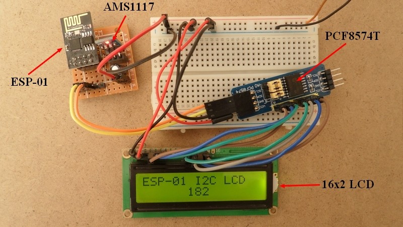
The video below shows my simple hardware circuit test:

Hello, I tried but it tells me the following message:
‘set_speed’ was not declared in this scope
Is it a library because I can’t find it?
thank you in advance