This tutorial shows how to build a simple real time clock & calendar (RTCC) using the ESP8266 NodeMCU board and DS1307 RTC integrated circuit where time and date are printed on ST7789 TFT display module.
The ST7789 TFT module contains a display controller with the same name: ST7789. It’s a color display that uses SPI interface protocol and requires 3, 4 or 5 control pins, it’s low cost and easy to use. This display is an IPS display, it comes in different sizes (1.3″, 1.54″ …) but all of them should have the same resolution of 240×240 pixel, this means it has 57600 pixels. This module works with 3.3V only and it does not support 5V.
TFT: Thin-Film Transistor.
SPI: Serial Peripheral Interface.
IPS: In-Plane Switching.
IIC (or I2C): Inter-Integrated Circuit.
To see how to interface the NodeMCU board with ST7789 TFT display, visit this post:
Interfacing ESP8266 NodeMCU with ST7789 TFT Display
Hardware Required:
- ESP8266 NodeMCU board (LoLin)
- ST7789 TFT display module (1.3″, 1.54″ …)
- DS1307 RTC —-> datasheet
- 32.768 kHz crystal oscillator
- 4 x 4.7k Ohm resistor
- 2 x push button
- 3V coin cell battery
- Micro USB cable (for programming and powering the whole circuit)
- Breadboard
- Jumper wires
NodeMCU with ST7789 TFT and DS1307 circuit:
Project circuit schematic diagram is shown below.
The ST7789 display module shown in project circuit diagram has 7 pins: (from right to left): GND (ground), VCC, SCL (serial clock), SDA (serial data), RES (reset), DC (or D/C: data/command) and BLK (back light).
Connecting the BLK pin is optional. The back light turns off when the BLK pin connected to the ground (GND).
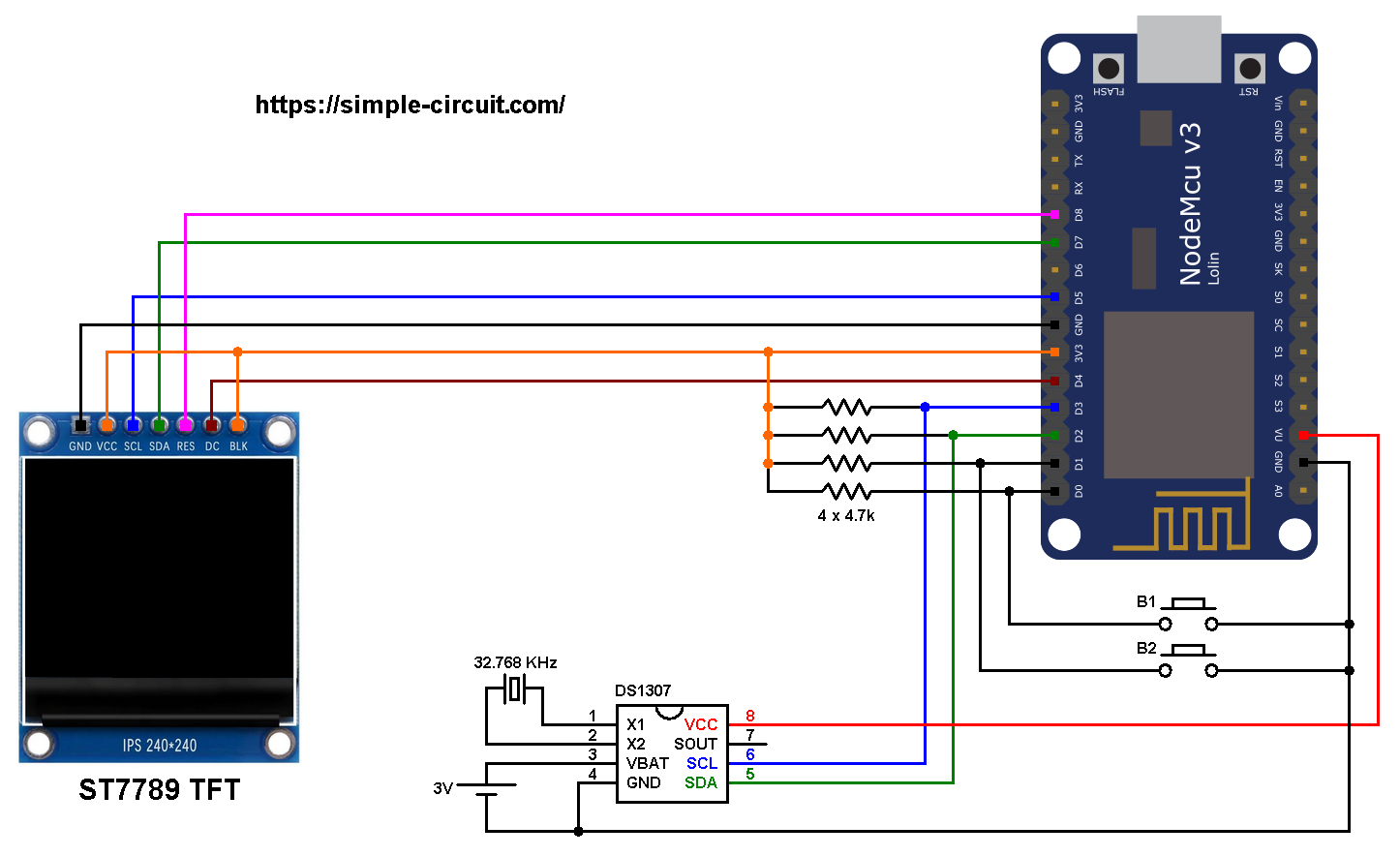
The ST7789 TFT display module is connected to the NodeMCU board as follows:
GND is connected to pin GND of the NodeMCU board,
VCC and BL are connected to pin 3V3,
SCL pin is connected to D5 (ESP8266EX GPIO14),
SDA pin is connected to D7 (ESP8266EX GPIO13),
RES pin is connected to D8 (ESP8266EX GPIO15),
DC pin is connected to D4 (ESP8266EX GPIO2).
If the display module has a CS pin (Chip Select) then it should be connected directly to NodeMCU GND pin.
Pins D5 (GPIO14) and D7 (GPIO13) are hardware SPI module pins of the ESP8266EX microcontroller respectively for SCK (serial clock) and MOSI (master-out slave-in).
The DS1307 SCL (serial clock) and SDA (serial data) pins are respectively connected to NodeMCU pins D2 (GPIO4) and D3 (GPIO0).
The DS1307 power input pin VCC is connected to NodeMCU VU pin (5V output).
The DS1307 operating voltage range is 4.5V – 5.5V and it may not work with 3.3V. The good thing is its high logic input starts from 2.2V.
A coin cell battery of 3 Volts is connected between VBAT and GND, it’s used to keep time running even if the main power source is cut. If the battery purpose is not needed then VBAT pin should be connected to GND.
The two push buttons which are connected to NodeMCU pins D0 (GPIO16) and D1 (GPIO5) are for setting time & date.
NodeMCU with ST7789 TFT and DS1307 code:
The following Arduino code requires 3 libraries from Adafruit Industries:
The first library is a driver for the ST7789 TFT display which can be installed from Arduino IDE library manager (Sketch —> Include Library —> Manage Libraries …, in the search box write “st7789” and install the one from Adafruit).
The second library is Adafruit graphics library which can be installed also from Arduino IDE library manager.
The 3rd library is for the DS1307 RTC, it may be installed using library manager (in the search box write “rtclib” and install the one from Adafruit).
The 3 libraries can be installed manually, first download them from the following 2 links:
Adafruit ST7789 TFT library —-> direct link
Adafruit graphics library —-> direct link
Adafruit RTC library —-> direct link
After the download, go to Arduino IDE —> Sketch —> Include Library —> Add .ZIP Library … and browse for the .zip file (previously downloaded).
The same thing for other library files.
Hints:
The previous 3 libraries (& Wire library) are included in the main code as follows:
1 2 3 4 | #include <Wire.h> // Wire library (required for I2C devices) #include <Adafruit_GFX.h> // Core graphics library #include <Adafruit_ST7789.h> // Hardware-specific library for ST7789 #include "RTClib.h" // RTC library |
The connection of ST7789 TFT display with the NodeMCU is as shown below where the display is connected to hardware SPI module of the NodeMCU (pins: SCK and MOSI):
1 2 3 4 5 6 7 8 | // ST7789 TFT module connections #define TFT_RST D8 // TFT RST pin is connected to NodeMCU pin D8 (GPIO15) #define TFT_DC D4 // TFT DC pin is connected to NodeMCU pin D4 (GPIO2) #define TFT_CS -1 // TFT CS pin is directly connected to GND // initialize ST7789 TFT library with hardware SPI module // SCK (CLK) ---> NodeMCU pin D5 (GPIO14) // MOSI(DIN) ---> NodeMCU pin D7 (GPIO13) Adafruit_ST7789 tft = Adafruit_ST7789(TFT_CS, TFT_DC, TFT_RST); |
And the TFT display is initialized using the following command:
1 2 | // if the display has CS pin try with SPI_MODE0 tft.init(240, 240, SPI_MODE2); // init ST7789 display 240x240 pixel |
The two push buttons are defined in the code as:
1 2 | const int button1 = D0; // button B1 is connected to NodeMCU D0 (GPIO16) const int button2 = D1; // button B2 is connected to NodeMCU D1 (GPIO5) |
Functions used in the code:
bool debounce (): this function is for button B1 debounce, returns 1 if button is debounced.
void RTC_display(): displays day of the week, date and time on the display.
byte edit(byte parameter): this function is for setting the real time clock, returns the edited parameter.
Rest of code is described through comments.
Full Arduino code:
1 2 3 4 5 6 7 8 9 10 11 12 13 14 15 16 17 18 19 20 21 22 23 24 25 26 27 28 29 30 31 32 33 34 35 36 37 38 39 40 41 42 43 44 45 46 47 48 49 50 51 52 53 54 55 56 57 58 59 60 61 62 63 64 65 66 67 68 69 70 71 72 73 74 75 76 77 78 79 80 81 82 83 84 85 86 87 88 89 90 91 92 93 94 95 96 97 98 99 100 101 102 103 104 105 106 107 108 109 110 111 112 113 114 115 116 117 118 119 120 121 122 123 124 125 126 127 128 129 130 131 132 133 134 135 136 137 138 139 140 141 142 143 144 145 146 147 148 149 150 151 152 153 154 155 156 157 158 159 160 161 162 163 164 165 166 167 168 169 170 171 172 173 174 175 176 177 178 179 180 181 182 | /************************************************************************** * * Interfacing ESP8266 NodeMCU with ST7789 TFT display (240x240 pixel) and DS1307 RTC. * This is a free software with NO WARRANTY. * http://simple-circuit.com/ * *************************************************************************/ #include <Wire.h> // Wire library (required for I2C devices) #include <Adafruit_GFX.h> // Core graphics library #include <Adafruit_ST7789.h> // Hardware-specific library for ST7789 #include "RTClib.h" // RTC library // ST7789 TFT module connections #define TFT_RST D8 // TFT RST pin is connected to NodeMCU pin D8 (GPIO15) #define TFT_DC D4 // TFT DC pin is connected to NodeMCU pin D4 (GPIO2) #define TFT_CS -1 // TFT CS pin is directly connected to GND // initialize ST7789 TFT library with hardware SPI module // SCK (CLK) ---> NodeMCU pin D5 (GPIO14) // MOSI(DIN) ---> NodeMCU pin D7 (GPIO13) Adafruit_ST7789 tft = Adafruit_ST7789(TFT_CS, TFT_DC, TFT_RST); // initialize RTC library RTC_DS1307 rtc; DateTime now; const int button1 = D0; // button B1 is connected to NodeMCU D0 (GPIO16) const int button2 = D1; // button B2 is connected to NodeMCU D1 (GPIO5) void setup(void) { // if the display has CS pin try with SPI_MODE0 tft.init(240, 240, SPI_MODE2); // init ST7789 display 240x240 pixel // if the screen is flipped, remove this command tft.setRotation(2); // fill the screen with black color tft.fillScreen(ST77XX_BLACK); tft.fillRect(0, 59, tft.width(), 2, ST77XX_BLUE); tft.fillRect(0, 150, tft.width(), 2, ST77XX_BLUE); tft.setTextWrap(false); // turn off text wrap option tft.setTextColor(ST77XX_WHITE, ST77XX_BLACK); // set text color to white and black background tft.setTextSize(2); // text size = 2 tft.setCursor(0, 10); // move cursor to position (0, 10) pixel tft.print("NODEMCU + ST7789 TFT"); tft.setCursor(48, 34); // move cursor to position (48, 34) pixel tft.print("+ DS1307 RTC"); tft.setTextSize(4); // text size = 4 tft.setTextColor(ST77XX_MAGENTA, ST77XX_BLACK); tft.setCursor(64, 163); tft.print("TIME:"); pinMode(button1, INPUT); pinMode(button2, INPUT); Wire.begin(D2, D3); // set I2C pins [SDA = D2, SCL = D3], default clock is 100kHz rtc.begin(); // initialize RTC chip } // a small function for button1 (B1) debounce bool debounce () { byte count = 0; for(byte i = 0; i < 5; i++) { if ( !digitalRead(button1) ) count++; delay(10); } if(count > 2) return 1; else return 0; } void RTC_display() { char dow_matrix[7][10] = {"SUNDAY", "MONDAY", "TUESDAY", "WEDNESDAY", "THURSDAY", "FRIDAY", "SATURDAY"}; byte x_pos[7] = {50, 50, 38, 14, 26, 50, 26}; static byte previous_dow = 8; // print day of the week if( previous_dow != now.dayOfTheWeek() ) { previous_dow = now.dayOfTheWeek(); tft.fillRect(14, 72, 216, 28, ST77XX_BLACK); // draw rectangle (erase day from the display) tft.setCursor(x_pos[previous_dow], 72); tft.setTextColor(ST77XX_CYAN, ST77XX_BLACK); // set text color to cyan and black background tft.print( dow_matrix[now.dayOfTheWeek()] ); } // print date tft.setCursor(1, 111); tft.setTextColor(ST77XX_YELLOW, ST77XX_BLACK); // set text color to yellow and black background tft.printf( "%02u-%02u-%04u", now.day()%100, now.month()%100, now.year() ); // print time tft.setCursor(26, 202); tft.setTextColor(ST77XX_GREEN, ST77XX_BLACK); // set text color to green and black background tft.printf( "%02u:%02u:%02u", now.hour()%100, now.minute()%100, now.second()%100 ); } byte edit(byte parameter) { static byte i = 0, y_pos, x_pos[5] = {1, 73, 193, 26, 98}; if(i < 3) { tft.setTextColor(ST77XX_YELLOW, ST77XX_BLACK); // set text color to yellow and black background y_pos = 111; } else { tft.setTextColor(ST77XX_GREEN, ST77XX_BLACK); // set text color to green and black background y_pos = 202; } while( debounce() ); // call debounce function (wait for B1 to be released) while(true) { while( !digitalRead(button2) ) { // while B2 is pressed parameter++; if(i == 0 && parameter > 31) // if day > 31 ==> day = 1 parameter = 1; if(i == 1 && parameter > 12) // if month > 12 ==> month = 1 parameter = 1; if(i == 2 && parameter > 99) // if year > 99 ==> year = 0 parameter = 0; if(i == 3 && parameter > 23) // if hours > 23 ==> hours = 0 parameter = 0; if(i == 4 && parameter > 59) // if minutes > 59 ==> minutes = 0 parameter = 0; tft.setCursor(x_pos[i], y_pos); tft.printf("%02u", parameter); delay(200); // wait 200ms } tft.fillRect(x_pos[i], y_pos, 44, 28, ST77XX_BLACK); unsigned long previous_m = millis(); while( (millis() - previous_m < 250) && digitalRead(button1) && digitalRead(button2)) ; tft.setCursor(x_pos[i], y_pos); tft.printf("%02u", parameter); previous_m = millis(); while( (millis() - previous_m < 250) && digitalRead(button1) && digitalRead(button2)) ; if(!digitalRead(button1)) { // if button B1 is pressed i = (i + 1) % 5; // increment 'i' for the next parameter return parameter; // return parameter value and exit } } } // main loop void loop() { if( !digitalRead(button1) ) // if B1 is pressed if( debounce() ) // call debounce function (make sure B1 is pressed) { while( debounce() ); // call debounce function (wait for B1 to be released) byte day = edit( now.day() ); // edit date byte month = edit( now.month() ); // edit month byte year = edit( now.year() - 2000 ); // edit year byte hour = edit( now.hour() ); // edit hours byte minute = edit( now.minute() ); // edit minutes // write time & date data to the RTC chip rtc.adjust(DateTime(2000 + year, month, day, hour, minute, 0)); while(debounce()); // call debounce function (wait for button B1 to be released) } now = rtc.now(); // read current time and date from the RTC chip RTC_display(); // display time & calendar delay(100); // wait 100 ms } // end of code. |
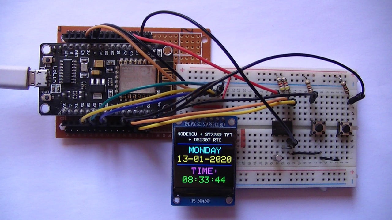
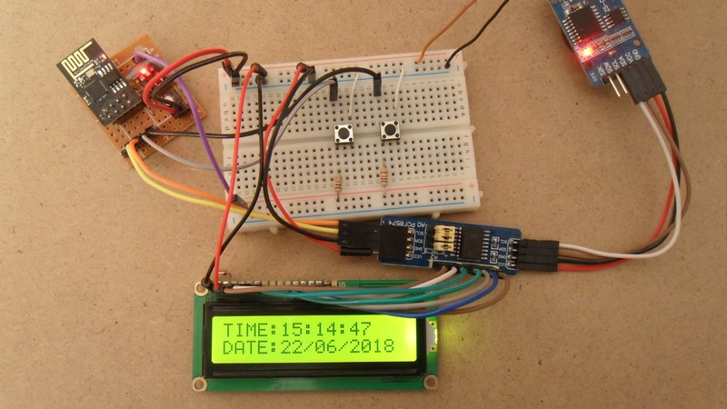
The following image shows my hardware circuit:
Related Project:
ESP8266 NodeMCU with ST7789 TFT and DS3231 RTC

what software did you use to make the circuit diagrams?