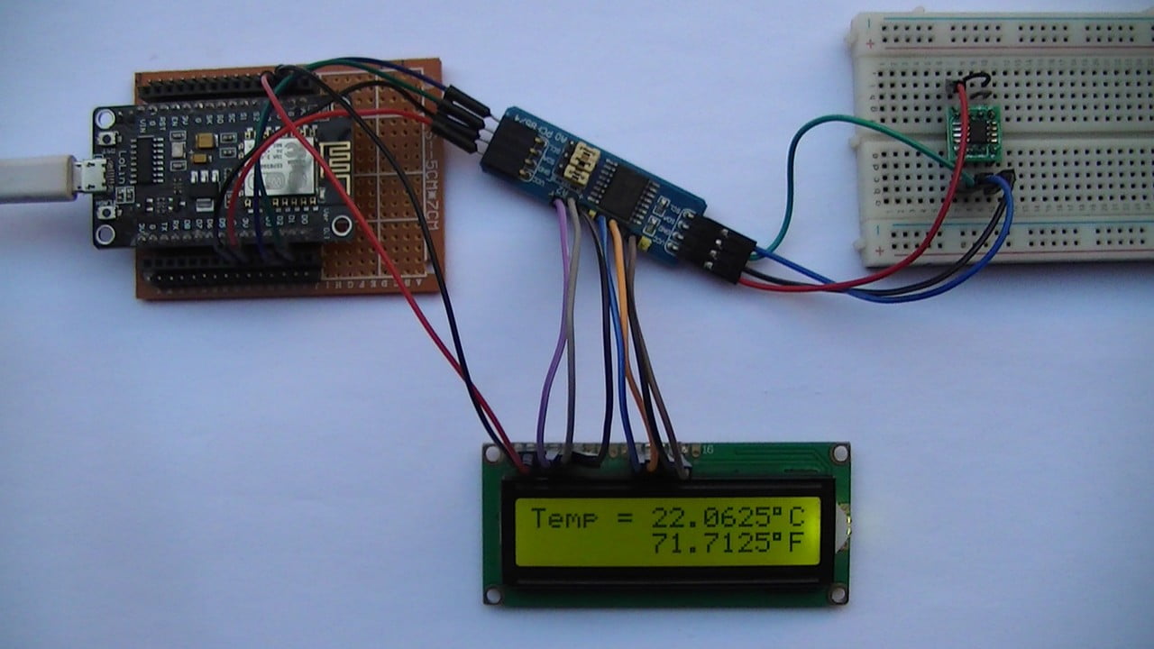
This post shows how to interface ESP8266 NodeMCU board (ESP-12E) with DS1631 digital temperature sensor where temperature values (in degrees Celsius and degrees Fahrenheit) are printed on 1602 LCD screen.
The 1602 LCD used in this project is connected to PCF8574 I2C I/O expander which allows it to communicate with NodeMCU board via I2C bus, this minimizes number of pins required and also may simplify the circuit.
The I2C bus uses only two pins: SDA (serial data) and SCL (serial clock).
This interfacing should also work with DFRobot I2C LCD displays.
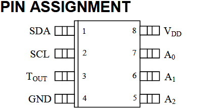
About the DS1631 (from datasheet):
The DS1631 digital thermometer and thermostat from Maxim Integrated provide 9, 10, 11, or 12-bit temperature readings over a -55 °C to +12 °C range. The DS1631 thermometer accuracy is ±0.5 °C from 0 °C to +70 °C with 3.0V ≤ VDD ≤ 5.5V. The thermostat on DS1631 provides custom hysteresis with user-defined trip points (TH and TL). The TH and TL registers and thermometer configuration settings are stored in NV EEPROM so they can be programmed prior to installation.
Benefits and features:
- Operating temperature range: -55 °C to +125 °C (-67 °F to +257 °F).
- ±0.5 °C Accuracy over 0 °C to +70 °C range.
- User-Selectable output resolution from 9 bits to 12 bits.
- Reduce cost with no external components.
- Up to eight devices can operate on a 2-wire bus.
- Flexible and nonvolatile user-defined thermostatic modes with custom hysteresis.
- Available in 8-Pin μSOP, SO and DIP packages.
The I2C LCD display and the DS1631 sensor can be connected to the same I2C bus where the NodeMCU board microcontroller can talk with both devices (one at a time).
Hardware Required:
- ESP8266 NodeMCU board (LoLin)
- DS1631 temperature sensor —-> datasheet
- 1602 LCD screen
- PCF8574 I/O expander (or PCF8574A) —-> PCF8574 datasheet
- 3 x 10k ohm resistor
- 2 x 4.7k ohm resistor
- 330 ohm resistor
- 10k ohm variable resistor or potentiometer
- micro USB cable (for programming and powering the circuit)
- Breadboard
- Jumper wires
NodeMCU with DS1631 sensor and 1602 LCD circuit:
Project circuit diagram is shown below.
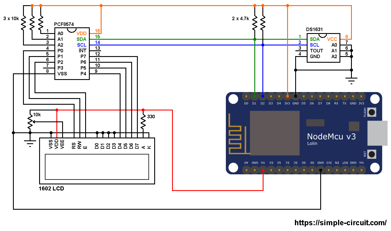
The PCF8574 I/O expander is powered with 3.3V that comes from the NodeMCU board (PCF8574 VDD pin is connected to NodeMCU 3V3 pin and VSS is connected to GND).
SDA and SCL pins of the PCF8574 are respectively connected to NodeMCU pins D1 and D2.
A0, A1 and A2 pins of the PCF8574 are address select pins, they decide the I2C address of the chip. In this example each pin is connected to VDD (3.3V) through a 10k ohm resistor (placing the 10k resistor is optional, each pin can be connected directly to VDD).
The I2C address of the PCF8574 is: 0x20 | A2+A1+A0
In the circuit above the three pins A2, A1 and A0 are connected to VDD ( each one through 10k resistor). That means the I2C address is equal to 0x20 | 7 = 0x27.
If the PCF8574A is used instead of the PCF8574 then the I2C address is: 0x38 | 7 = 0x3F.
LCD data pins are connected to the PCF8574 where: RS, RW, E, D4, D5, D6 and D7 are respectively connected to P0, P1, P2, P4, P5, P6 and P7.
The 1602 LCD is powered with 5V from the NodeMCU board where its VDD pin is connected to NodeMCU pin VU and VSS is connected to GND.
The 1602 LCD operating voltage range is 4.5V – 5.5V and it may not work with 3.3V. The good thing is it accepts 3.3V on its I/O pins.
Other LCD pins are connected as follows:
VSS, RW, D0, D1, D2, D3 and K are connected to NodeMCU GND pin,
VEE to the 10k ohm variable resistor (or potentiometer) output,
A is connected to NodeMCU VU pin (5V) through 330 ohm resistor.
VEE pin is used to control the contrast of the LCD. A (anode) and K (cathode) are backlight LED pins.
The DS1631 temperature sensor SDA (serial data) and SCL (serial clock) pins are respectively connected to NodeMCU board pins D1 and D2 (PCF8574 and DS1631 are connected to the same I2C bus). The DS1631 is supplied with 3.3V from the NodeMCU board.
The three pins: A0, A1 and A2 are slave address select pins, they are connected to ground, therefore the DS1631 takes an address of 0x48 (1001+A2+A1+A0).
NodeMCU with DS1631 sensor and 1602 LCD code:
To be able to compile project code with no error, a library for the I2C LCD display is required, download link is below:
LiquidCrystal_I2C Library —-> direct link
After the download, go to Arduino IDE —> Sketch —> Include Library —> Add .ZIP Library … and browse for library .zip file (previously downloaded).
Hints:
The I2C LCD library is initialized with address of 0x27, 2 rows and 16 columns:
1 2 | // configure LiquidCrystal_I2C library with 0x27 address, 16 columns and 2 rows LiquidCrystal_I2C lcd(0x27, 16, 2); |
Since the address pins of the DS1631 sensor (A2, A1 and A0) are connected to NodeMCU GND, its I2C slave address is 0x48 and it is defined in the code as shown below:
1 2 3 | // define DS1631 I2C slave address (1001+A2+A1+A0) // A2, A1 & A0 connected to GND --> 1001000 = 0x48 #define DS1631_ADDRESS 0x48 |
In the Arduino code below there is a function named ds1631_temperature(), it is used to read temperature values from the DS1631 sensor.
The previous function returns a signed 2-byte number which is actual temperature value (in °C) multiplied by 16 (why 16? —> because we’re working with 12-bit resolution).
For example if the returned value equals to 209, this means actual temperature is equal to 209/16 = 13.0625 °C.
To get the value of temperature in degrees Fahrenheit (°F), I used the function below:
1 | int32_t f_temp = (int32_t)c_temp * 90/5 + 5120; // 5120 = 32 x 16 x 10 |
This function is just from the common one: °F = °C x 9/5 + 32.
Since the temperature in °C is multiplied by 16 the constant number 32 also needs to be multiplied by 16.
To get the °F temperature with no floating number, I multiplied every thing by 10.
This function gives the actual value of the temperature in °F multiplied by 160 (actual °F = f_temp/160).
Since the DS1631 is used with 12-bit resolution, we get the temperature in °C as shown below (example):
1 | lcd.printf(" %02u.%04u%cC", c_temp/16, (c_temp & 0x0F) * 625, 223); |
Again, why 16 and 625? —> Because we are working with 12-bit resolution (step = ± 0.0625).
The resolution of this thermometer is 0.0625°C (0.1125°F).
Full Arduino code:
1 2 3 4 5 6 7 8 9 10 11 12 13 14 15 16 17 18 19 20 21 22 23 24 25 26 27 28 29 30 31 32 33 34 35 36 37 38 39 40 41 42 43 44 45 46 47 48 49 50 51 52 53 54 55 56 57 58 59 60 61 62 63 64 65 66 67 68 69 70 71 72 73 74 75 76 77 78 79 80 81 82 83 84 85 86 87 88 89 90 | /************************************************************************** * * Interfacing ESP8266 NodeMCU with 1602 I2C LCD screen and DS1631 * temperature sensor. * This is a free software with NO WARRANTY. * http://simple-circuit.com/ * *************************************************************************/ #include <Wire.h> // include Wire library (required for I2C devices) #include <LiquidCrystal_I2C.h> // include I2C LCD library // configure LiquidCrystal_I2C library with 0x27 address, 16 columns and 2 rows LiquidCrystal_I2C lcd(0x27, 16, 2); // define DS1631 I2C slave address (1001+A2+A1+A0) // A2, A1 & A0 connected to GND --> 1001000 = 0x48 #define DS1631_ADDRESS 0x48 void setup(void) { lcd.begin(D1, D2); // initialize I2C LCD module (SDA = D1, SCL = D2) lcd.backlight(); // turn backlight ON lcd.setCursor(0, 0); // move cursor to column 0, row 0 [position (0, 0)] lcd.print("Temp ="); // initialize DS1631 sensor Wire.beginTransmission(DS1631_ADDRESS); // connect to DS1631 (send DS1631 address) Wire.write(0xAC); // send configuration register address (Access Config) Wire.write(0x0C); // perform continuous conversion with 12-bit resolution Wire.beginTransmission(DS1631_ADDRESS); // send repeated start condition Wire.write(0x51); // send start temperature conversion command Wire.endTransmission(); // stop transmission and release the I2C bus } // main loop void loop() { delay(1000); // wait a second // get temperature in °C ( actual temperature in °C = c_temp/16) int16_t c_temp = ds1631_temperature(); // calculate temperature in °F (actual temperature in °F = f_temp/160) // °F = °C x 9/5 + 32 int32_t f_temp = (int32_t)c_temp * 90/5 + 5120; // 5120 = 32 x 16 x 10 // print temperature in °C lcd.setCursor(6, 0); // move cursor to position (6, 0) if(c_temp < 0) { // if temperature < 0 °C c_temp = abs(c_temp); // absolute value lcd.printf("-%02u.%04u%cC", c_temp/16, (c_temp & 0x0F) * 625, 223); } else { if (c_temp/16 >= 100) // if temperature >= 100.0 °C lcd.printf("%03u.%04u%cC", c_temp/16, (c_temp & 0x0F) * 625, 223); else lcd.printf(" %02u.%04u%cC", c_temp/16, (c_temp & 0x0F) * 625, 223); } // print temperature in °F lcd.setCursor(6, 1); // move cursor to position (6, 0) if(f_temp < 0) { // if temperature < 0 °F f_temp = abs(f_temp); // absolute value lcd.printf("-%02u.%04u%cF", (uint16_t)f_temp/160, (uint16_t)(f_temp*1000/16 % 10000), 223); } else { if (f_temp/160 >= 100) // if temperature >= 100.0 °F lcd.printf("%03u.%04u%cF", (uint16_t)f_temp/160, (uint16_t)(f_temp*1000/16 % 10000), 223); else lcd.printf(" %02u.%04u%cF", (uint16_t)f_temp/160, (uint16_t)(f_temp*1000/16 % 10000), 223); } } int16_t ds1631_temperature() { Wire.beginTransmission(DS1631_ADDRESS); // connect to DS1631 (send DS1631 address) Wire.write(0xAA); // read temperature command Wire.endTransmission(false); // send repeated start condition Wire.requestFrom(DS1631_ADDRESS, 2); // request 2 bytes from DS1631 and release I2C bus at end of reading uint8_t t_msb = Wire.read(); // read temperature MSB register uint8_t t_lsb = Wire.read(); // read temperature LSB register // calculate full temperature (raw value) int16_t raw_t = (int8_t)t_msb << 8 | t_lsb; raw_t >>= 4; return raw_t; } // end of code. |
Related Project:
NodeMCU with I2C LCD and DS1621 Temperature Sensor