This topic shows how to interface the SSD1306 OLED display with ESP8266 NodeMCU development board (ESP-12E). The display used in this project has a resolution of 128×64 Pixel and works in I2C mode, that means the NodeMCU communicates with the display using I2C communication protocol. The I2C protocol uses two lines: SDA (serial data) and SCL (serial clock). the SSD1306 requires 2 pins for the I2C bus and an additional reset pin (if the SSD1306 OLED board has a reset pin).
SSD1306 OLED driver for Arduino IDE:
Adafruit Industries provides a very nice library for the SSD1306 OLED, it can be easily installed using Arduino library manager (Sketch —> Include Library —> Library Manager), or manually by downloading it from the link below and adding it to Arduino libraries folder (C:\Program Files\Arduino\libraries):
Adafruit SSD1306 OLED library
Note that the Adafruit SSD1306 OLED driver supports 3 types: 128×64, 128×32 and 96×16 pixel, we can select between them in the driver header file Adafruit_SSD1306.h. Opening the file with a text editor such as the Arduino IDE gives (scroll down as shown):
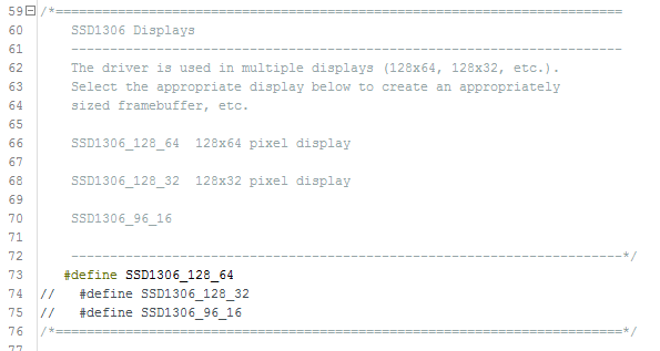
I commented the default display type #define SSD1306_128_32 and uncommented #define SSD1306_128_64 because I’m using 128×64 pixel display (0.96″).
We need an other library named Adafruit GFX (graphics library) which can be installed through Arduino library manager or manually by downloading it from the link below:
Adafruit GFX library
Hardware Required:
The components listed below are required for this project.
- ESP8266 NodeMCU module (ESP-12E)
- SSD1306 OLED display
- Breadboard
- Jumper wires
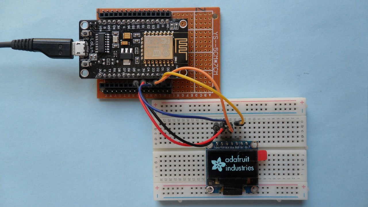
NodeMCU interfacing with SSD1306 OLED circuit:
The following image shows the circuit schematic diagram of the project.

and the second image shows fritzing breadboard circuit:
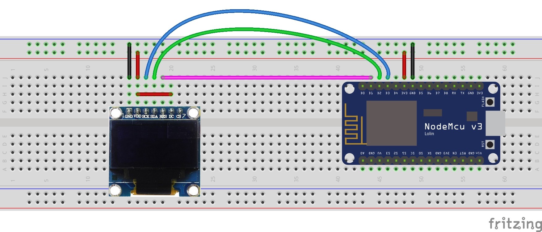
The SDA and SCL lines of the I2C bus come from GPIO4 (D2) and GPIO0 (D3) of the NodeMCU board (respectively), they are connected to SDA and SCL (SCK) pins of the SSD1306 display module.
Reset pin (RES) of the display module is connected to GPIO5 (D1) of the NodeMCU development board.
The SSD1306 display module is supplied with 3.3V which comes from the NodeMCU board.
NodeMCU interfacing with SSD1306 OLED code:
Project code is Adafruit library example code (ssd1306_128x64_i2c) with minor modifications. I added Wire.begin(4, 0); to configure the I2C bus pins. SDA is set to GPIO4 (D2) and SCL to GPIO0 (D3). The reset pin of the display module is connected to pin GPIO5 (D5):
#define OLED_RESET 5
The default clock frequency is 100kHz, for 400kHz clock uncomment line number 65 (L for long):
//Wire.setClock(400000L);
Full code is below:
1 2 3 4 5 6 7 8 9 10 11 12 13 14 15 16 17 18 19 20 21 22 23 24 25 26 27 28 29 30 31 32 33 34 35 36 37 38 39 40 41 42 43 44 45 46 47 48 49 50 51 52 53 54 55 56 57 58 59 60 61 62 63 64 65 66 67 68 69 70 71 72 73 74 75 76 77 78 79 80 81 82 83 84 85 86 87 88 89 90 91 92 93 94 95 96 97 98 99 100 101 102 103 104 105 106 107 108 109 110 111 112 113 114 115 116 117 118 119 120 121 122 123 124 125 126 127 128 129 130 131 132 133 134 135 136 137 138 139 140 141 142 143 144 145 146 147 148 149 150 151 152 153 154 155 156 157 158 159 160 161 162 163 164 165 166 167 168 169 170 171 172 173 174 175 176 177 178 179 180 181 182 183 184 185 186 187 188 189 190 191 192 193 194 195 196 197 198 199 200 201 202 203 204 205 206 207 208 209 210 211 212 213 214 215 216 217 218 219 220 221 222 223 224 225 226 227 228 229 230 231 232 233 234 235 236 237 238 239 240 241 242 243 244 245 246 247 248 249 250 251 252 253 254 255 256 257 258 259 260 261 262 263 264 265 266 267 268 269 270 271 272 273 274 275 276 277 278 279 280 281 282 283 284 285 286 287 288 289 290 291 292 293 294 295 296 297 298 299 300 301 302 303 304 305 306 307 308 309 310 311 312 313 314 315 316 317 318 319 320 321 322 323 324 325 326 327 328 329 330 331 332 333 334 335 336 337 338 339 340 341 342 343 344 345 346 347 348 349 350 351 352 353 354 355 356 357 358 359 360 361 362 363 364 365 366 367 368 369 370 371 372 373 374 375 376 377 378 | /********************************************************************* This is an example for our Monochrome OLEDs based on SSD1306 drivers Pick one up today in the adafruit shop! ------> http://www.adafruit.com/category/63_98 This example is for a 128x64 size display using I2C to communicate 3 pins are required to interface (2 I2C and one reset) Adafruit invests time and resources providing this open source code, please support Adafruit and open-source hardware by purchasing products from Adafruit! Written by Limor Fried/Ladyada for Adafruit Industries. BSD license, check license.txt for more information All text above, and the splash screen must be included in any redistribution *********************************************************************/ #include <Wire.h> #include <Adafruit_GFX.h> #include <Adafruit_SSD1306.h> #define OLED_RESET 5 // define SSD1306 OLED reset at GPIO5 (NodeMCU D1) Adafruit_SSD1306 display(OLED_RESET); #define NUMFLAKES 10 #define XPOS 0 #define YPOS 1 #define DELTAY 2 #define LOGO16_GLCD_HEIGHT 16 #define LOGO16_GLCD_WIDTH 16 static const unsigned char PROGMEM logo16_glcd_bmp[] = { B00000000, B11000000, B00000001, B11000000, B00000001, B11000000, B00000011, B11100000, B11110011, B11100000, B11111110, B11111000, B01111110, B11111111, B00110011, B10011111, B00011111, B11111100, B00001101, B01110000, B00011011, B10100000, B00111111, B11100000, B00111111, B11110000, B01111100, B11110000, B01110000, B01110000, B00000000, B00110000 }; #if (SSD1306_LCDHEIGHT != 64) #error("Height incorrect, please fix Adafruit_SSD1306.h!"); #endif void setup() { Serial.begin(9600); Wire.begin(4, 0); // set I2C pins [SDA = GPIO4 (D2), SCL = GPIO0 (D3)], default clock is 100kHz // by default, we'll generate the high voltage from the 3.3v line internally! (neat!) display.begin(SSD1306_SWITCHCAPVCC, 0x3D); // initialize with the I2C addr 0x3D (for the 128x64) // init done //Wire.setClock(400000L); // uncomment this to set I2C clock to 400kHz // Show image buffer on the display hardware. // Since the buffer is intialized with an Adafruit splashscreen // internally, this will display the splashscreen. display.display(); delay(2000); // Clear the buffer. display.clearDisplay(); // draw a single pixel display.drawPixel(10, 10, WHITE); // Show the display buffer on the hardware. // NOTE: You _must_ call display after making any drawing commands // to make them visible on the display hardware! display.display(); delay(2000); display.clearDisplay(); // draw many lines testdrawline(); display.display(); delay(2000); display.clearDisplay(); // draw rectangles testdrawrect(); display.display(); delay(2000); display.clearDisplay(); // draw multiple rectangles testfillrect(); display.display(); delay(2000); display.clearDisplay(); // draw mulitple circles testdrawcircle(); display.display(); delay(2000); display.clearDisplay(); // draw a white circle, 10 pixel radius display.fillCircle(display.width()/2, display.height()/2, 10, WHITE); display.display(); delay(2000); display.clearDisplay(); testdrawroundrect(); delay(2000); display.clearDisplay(); testfillroundrect(); delay(2000); display.clearDisplay(); testdrawtriangle(); delay(2000); display.clearDisplay(); testfilltriangle(); delay(2000); display.clearDisplay(); // draw the first ~12 characters in the font testdrawchar(); display.display(); delay(2000); display.clearDisplay(); // draw scrolling text testscrolltext(); delay(2000); display.clearDisplay(); // text display tests display.setTextSize(1); display.setTextColor(WHITE); display.setCursor(0,0); display.println("Hello, world!"); display.setTextColor(BLACK, WHITE); // 'inverted' text display.println(3.141592); display.setTextSize(2); display.setTextColor(WHITE); display.print("0x"); display.println(0xDEADBEEF, HEX); display.display(); delay(2000); display.clearDisplay(); // miniature bitmap display display.drawBitmap(30, 16, logo16_glcd_bmp, 16, 16, 1); display.display(); delay(1); // invert the display display.invertDisplay(true); delay(1000); display.invertDisplay(false); delay(1000); display.clearDisplay(); // draw a bitmap icon and 'animate' movement testdrawbitmap(logo16_glcd_bmp, LOGO16_GLCD_HEIGHT, LOGO16_GLCD_WIDTH); } void loop() { } void testdrawbitmap(const uint8_t *bitmap, uint8_t w, uint8_t h) { uint8_t icons[NUMFLAKES][3]; // initialize for (uint8_t f=0; f< NUMFLAKES; f++) { icons[f][XPOS] = random(display.width()); icons[f][YPOS] = 0; icons[f][DELTAY] = random(5) + 1; Serial.print("x: "); Serial.print(icons[f][XPOS], DEC); Serial.print(" y: "); Serial.print(icons[f][YPOS], DEC); Serial.print(" dy: "); Serial.println(icons[f][DELTAY], DEC); } while (1) { // draw each icon for (uint8_t f=0; f< NUMFLAKES; f++) { display.drawBitmap(icons[f][XPOS], icons[f][YPOS], bitmap, w, h, WHITE); } display.display(); delay(200); // then erase it + move it for (uint8_t f=0; f< NUMFLAKES; f++) { display.drawBitmap(icons[f][XPOS], icons[f][YPOS], bitmap, w, h, BLACK); // move it icons[f][YPOS] += icons[f][DELTAY]; // if its gone, reinit if (icons[f][YPOS] > display.height()) { icons[f][XPOS] = random(display.width()); icons[f][YPOS] = 0; icons[f][DELTAY] = random(5) + 1; } } } } void testdrawchar(void) { display.setTextSize(1); display.setTextColor(WHITE); display.setCursor(0,0); for (uint8_t i=0; i < 168; i++) { if (i == '\n') continue; display.write(i); if ((i > 0) && (i % 21 == 0)) display.println(); } display.display(); delay(1); } void testdrawcircle(void) { for (int16_t i=0; i<display.height(); i+=2) { display.drawCircle(display.width()/2, display.height()/2, i, WHITE); display.display(); delay(1); } } void testfillrect(void) { uint8_t color = 1; for (int16_t i=0; i<display.height()/2; i+=3) { // alternate colors display.fillRect(i, i, display.width()-i*2, display.height()-i*2, color%2); display.display(); delay(1); color++; } } void testdrawtriangle(void) { for (int16_t i=0; i<min(display.width(),display.height())/2; i+=5) { display.drawTriangle(display.width()/2, display.height()/2-i, display.width()/2-i, display.height()/2+i, display.width()/2+i, display.height()/2+i, WHITE); display.display(); delay(1); } } void testfilltriangle(void) { uint8_t color = WHITE; for (int16_t i=min(display.width(),display.height())/2; i>0; i-=5) { display.fillTriangle(display.width()/2, display.height()/2-i, display.width()/2-i, display.height()/2+i, display.width()/2+i, display.height()/2+i, WHITE); if (color == WHITE) color = BLACK; else color = WHITE; display.display(); delay(1); } } void testdrawroundrect(void) { for (int16_t i=0; i<display.height()/2-2; i+=2) { display.drawRoundRect(i, i, display.width()-2*i, display.height()-2*i, display.height()/4, WHITE); display.display(); delay(1); } } void testfillroundrect(void) { uint8_t color = WHITE; for (int16_t i=0; i<display.height()/2-2; i+=2) { display.fillRoundRect(i, i, display.width()-2*i, display.height()-2*i, display.height()/4, color); if (color == WHITE) color = BLACK; else color = WHITE; display.display(); delay(1); } } void testdrawrect(void) { for (int16_t i=0; i<display.height()/2; i+=2) { display.drawRect(i, i, display.width()-2*i, display.height()-2*i, WHITE); display.display(); delay(1); } } void testdrawline() { for (int16_t i=0; i<display.width(); i+=4) { display.drawLine(0, 0, i, display.height()-1, WHITE); display.display(); delay(1); } for (int16_t i=0; i<display.height(); i+=4) { display.drawLine(0, 0, display.width()-1, i, WHITE); display.display(); delay(1); } delay(250); display.clearDisplay(); for (int16_t i=0; i<display.width(); i+=4) { display.drawLine(0, display.height()-1, i, 0, WHITE); display.display(); delay(1); } for (int16_t i=display.height()-1; i>=0; i-=4) { display.drawLine(0, display.height()-1, display.width()-1, i, WHITE); display.display(); delay(1); } delay(250); display.clearDisplay(); for (int16_t i=display.width()-1; i>=0; i-=4) { display.drawLine(display.width()-1, display.height()-1, i, 0, WHITE); display.display(); delay(1); } for (int16_t i=display.height()-1; i>=0; i-=4) { display.drawLine(display.width()-1, display.height()-1, 0, i, WHITE); display.display(); delay(1); } delay(250); display.clearDisplay(); for (int16_t i=0; i<display.height(); i+=4) { display.drawLine(display.width()-1, 0, 0, i, WHITE); display.display(); delay(1); } for (int16_t i=0; i<display.width(); i+=4) { display.drawLine(display.width()-1, 0, i, display.height()-1, WHITE); display.display(); delay(1); } delay(250); } void testscrolltext(void) { display.setTextSize(2); display.setTextColor(WHITE); display.setCursor(10,0); display.clearDisplay(); display.println("scroll"); display.display(); delay(1); display.startscrollright(0x00, 0x0F); delay(2000); display.stopscroll(); delay(1000); display.startscrollleft(0x00, 0x0F); delay(2000); display.stopscroll(); delay(1000); display.startscrolldiagright(0x00, 0x07); delay(2000); display.startscrolldiagleft(0x00, 0x07); delay(2000); display.stopscroll(); } |
After I build my protoboard circuit I got a result as shown in the following video where ESP8266 ESP-01 module is used:
ESP8266 Projects with SSD1306 OLED display:
ESP8266 NodeMCU interfacing with DHT11 sensor and SSD1306
Interfacing NodeMCU with DHT22 sensor and SSD1306 OLED
NodeMCU Interfacing with SSD1306 and DS18B20 temperature sensor
Real time clock using NodeMCU, DS3231 and SSD1306 OLED
NodeMCU Internet clock with SSD1306 display | IoT Projects
NodeMCU Internet weather station with SSD1306 OLED | IoT Projects
NodeMCU Internet clock and weather station | IoT Projects
ESP8266 NodeMCU Interface with SSD1306 OLED and BMP280 sensor
NodeMCU weather station with SSD1306 OLED and BME280 sensor
Interfacing NodeMCU with LM35 temperature sensor