This is another post that shows how to measure AC current using Arduino uno board and current transformer with TRMS calculations.
The current transformer (CT) used in this project has a turns ratio of 2000:1 and a rated current of 20A.
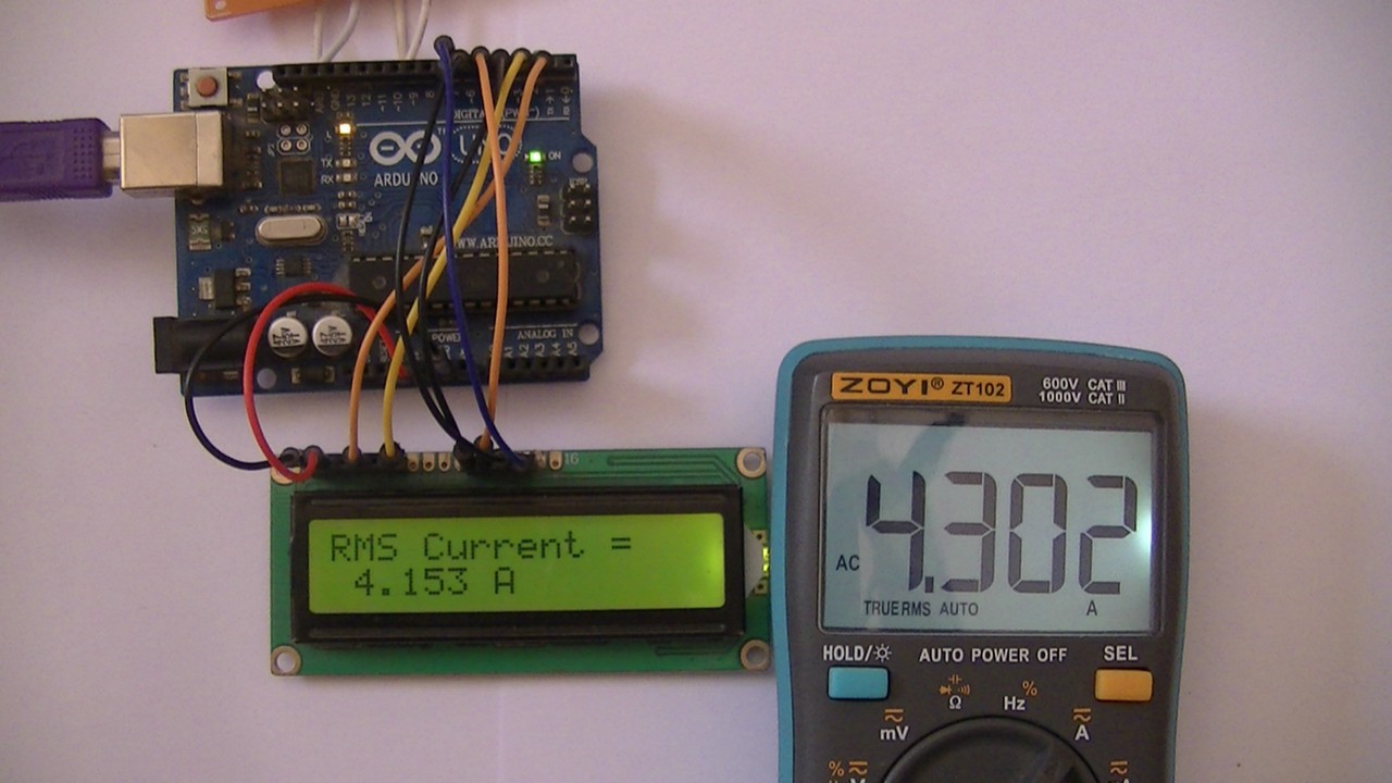
A 1602 LCD connected to the Arduino board is used to display current values, the Arduino also sends the same values to the Laptop which can be viewed using serial monitor.
Hints:
No warranty is provided with this project, so do it at your own risk!
A part of project circuit may be subjected to high voltage which is very harmful to human body, so be-careful!
Abbreviations:
AC: Alternating Current
DC: Direct Current
TRMS: True Root Mean Square
ADC: Analog-to-Digital Converter
CT: Current Transformer
PCB: Printed Circuit Board
DIY: Do It Yourself
In the last post, I built another AC current measurement circuit with auto-ranging using Arduino uno and 50:5 current transformer, you can find post link below:
AC Current Measurement using Arduino and Current Transformer
About Current Transformer:
Current transformer (CT) is an instrument transformer which is used to step down current by the inverse of its turns ratio. The secondary of the current transformer has more tuns than the primary. Today, a typical CT secondary rated current is 5A or 1A, however, many CTs have smaller rated secondary current such as 20mA, 40mA …
Generally, current transformer is used to transmit current image information signal to a measuring instrument, protective device or similar apparatus.
Usually, the current transformer ratio is stated to include primary and secondary current ratings, for example 600:5, means that a 600A in the primary is converted into 5A in the secondary.
When current is passing through the primary of the CT, the secondary should be always kept shorted either through a shunt resistor (or meter coils) or through a shorting switch (for example jumper) because the secondary may produce very high and harmful potential.
Another thing should be noted with CT is its rated apparent power, for example 10VA, or its maximum burden impedance.
Interfacing Arduino with Current Transformer circuit:
Project circuit diagram is shown below (click on the image for better view).

Note that in the circuit there is 1 ground only which is the same as the Arduino ground (GND).
The Arduino uno board is represented by U1.
For circuit resistors, a low tolerance resistors should be used, let’s say 1% or lower, lower tolerance gives better accuracy!
Hardware required:
This is a summary of circuit required parts (circuit schematic diagram may contain some component parameters not mentioned below).
- Arduino Uno or equivalent board such as Arduino Nano
- 2000/1A current transformer
- MCP6022 op amp (U2) —> details
- MCP1501-10 buffered voltage reference (U3) —> details
- 1602 LCD screen
- 2 x 20k resistor (R9, R10)
- 4 x 10k resistor (R2, R3, R6, R12)
- 330 Ohm resistor (R5)
- 100 Ohm resistor (R7)
- 68 Ohm resistor (R1)
- 20 Ohm resistor (R8)
- 10 Ohm resistor (R11)
- 10k variable resistor (R24)
- 2 x 2.2 µF capacitor (C4, C5)
- 2 x 0.1 µF capacitor (C1, C2)
- 2 x 10 nF capacitor (C3)
Circuit description:
As shown in project circuit schematic diagram above, the current transformer which is noted as T1 has the following characteristics:
CT name (as noted): ZDCT004GL
Primary rated current: 20 A
Secondary rated current: 10 mA
Turns ratio: 20/0.01 = 2000
Max burden resistance (sampling resistance): 100 Ohm
The wire that feeds the load passes through the hole of the current transformer. Note that only 1 wire of a single phase load has to be used to measure the AC current, the CT will read 0A if the two wires (phase and natural) are used because the sum of the magnetic field produced by the 2 wires is 0!
Other types of current transformers may be used such as 1000/1 but its ratio needs to be modified in the Arduino code.
The secondary of the current transformer is connected to resistor with resistance of 20 Ohm (R8), other resistance values may be used (up to 100 Ohm).
With R8 = 20 Ohm and at rated primary current of 20A, the voltage drop across R8 is:
V = 20 x 10mA = 200mV AC.
The Arduino microcontroller ADC can’t read voltages lower than 0 (negative voltages) and we need to shift the AC signal to the positive side, this can be done by adding a DC offset to the AC signal.
For that I used an amplifier circuit which firstly filters the signal and secondly adds a dc offset of 0.512V. The main component is MCP6022 (U2) where just 1 op amp is used. It is supplied with 5V from the Arduino board (pin 8 of U2 is connected to Arduino 5V pin, and pin 4 of U2 is connected to any of Arduino GND pins).
This circuit has a gain of 1 and dc offset of 0.512V.
For the U2 IC and instead of MCP6022, other op amp ICs may be used such as MCP6062 (or MCP6061).
Before the AC signal goes to Arduino analog channel 0 (A0) it passes through an RC low pass filter which comprised of R1 and C1. The frequency of this filter can be simply calculated using the equation below:
f = 1/(2 x π x R x C) = 23.4kHz
I used the MCP1501-10 (U3) to get a precise voltage of 1.024V which is then used as a positive voltage reference for the Arduino microcontroller ADC module. The MCP1501-10 is also supplied from the Arduino board with 5V. Its output is filtered and connected to the Arduino AREF pin.
The 1602 LCD screen (2 rows and 16 columns) is used to display the value of the current flows through the current transformer (load current), it is connected to the Arduino board as follows:
RS —> Arduino digital pin 2
E —> Arduino digital pin 3
D4 —> Arduino digital pin 4
D5 —> Arduino digital pin 5
D6 —> Arduino digital pin 6
D7 —> Arduino digital pin 7
VSS, RW, D0, D1, D2, D3 and K are connected to GND,
VEE to the 10k Ohms variable resistor (or potentiometer) output,
VDD to Arduino 5V and A to Arduino 5V through 330 ohm resistor.
VEE pin is used to control the contrast of the LCD. A (anode) and K (cathode) are the back light LED pins.
Interfacing Arduino with Current Transformer code:
Project code is the one below, it was tested with Arduino UNO board.
The code tries to calculate RMS values for symmetrical AC signal applied to analog channel 0. It can measure AC currents only.
Simply the average (mean or DC offset) value in discrete-time is the sum of all sample values divided by number of samples:
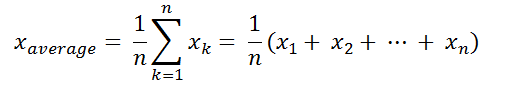
And the RMS value in discrete-time can be calculated using the following equation:

The Arduino uno board microcontroller (ATmega328P) contains a 10-bit ADC module, the positive voltage reference is 1.024V means that a 1.024V is digitally represented by 1023 and 0V is represented by 0 (1 digit for every 1mV).
To get more precise and higher resolution readings, I wrote a simple code to use what’s known as oversampling and decimation technique to add another 2 bits to the 10 bits of the ADC. This gives us a total of useful 12-bit words.
Firstly, I declared an array of 256 elements named ‘r_array’ , it is used to store reading samples which are used later to calculate average (dc offset) and RMS values.
With oversampling of 2 bits, we’ve to do 16 analog readings for each element of the ‘r_array’ variable. These readings are summed and divided by 4, where 16 = 4² and 4 = 2² and this ² is number of oversampling bits.
Oversampling code is the one below:
1 2 3 4 5 6 7 8 | // read voltage at INPUT_CHANNEL 'n' times and save data to 'r_array' for (uint16_t i = 0; i < n; i++) { // adding another 2 bits using oversampling technique for (uint16_t j = 0; j < 16; j++) { r_array[i] += analogRead(INPUT_CHANNEL); } r_array[i] /= 4; } |
Full Arduino code:
1 2 3 4 5 6 7 8 9 10 11 12 13 14 15 16 17 18 19 20 21 22 23 24 25 26 27 28 29 30 31 32 33 34 35 36 37 38 39 40 41 42 43 44 45 46 47 48 49 50 51 52 53 54 55 56 57 58 59 60 61 62 63 64 65 66 67 68 69 70 71 72 73 74 75 76 77 78 79 80 81 82 83 84 85 86 87 88 89 90 91 92 93 94 | /************************************************************************ * * AC Current measurement with Arduino and current transformer - 2nd Project. * Calculated RMS current values are printed on 1602 LCD screen and serial monitor. * This is a free software with NO WARRANTY - Use it at your own risk! * http://simple-circuit.com/ * ************************************************************************/ #include <LiquidCrystal.h> // include Arduino LCD library // LCD module connections (RS, E, D4, D5, D6, D7) LiquidCrystal lcd(2, 3, 4, 5, 6, 7); // define analog channel input #define INPUT_CHANNEL A0 // other definitions #define CT_RATIO 2000 // current transformer ratio 2000/1 = 2000 #define SHUNT_RES 20 // shunt resistor connected to CT secondary = 20 Ohm #define REF_VOLTAGE 1024 // reference voltage for ADC, in millivolts // variables const uint16_t n = 256; // total number of samples (readings) - without oversampling uint16_t r_array[n]; // readings array void setup(void) { Serial.begin(9600); lcd.begin(16, 2); // set up the LCD's number of columns and rows lcd.setCursor(0, 0); // move cursor to column 0, row 0 [position (0, 0)] lcd.print("RMS Current ="); analogReference(EXTERNAL); // set positive reference voltage to external } void loop() { float dc_offset = 0; float rms_voltage = 0; for (uint16_t i = 0; i < n; i++) r_array[i] = 0; // read voltage at INPUT_CHANNEL 'n' times and save data to 'r_array' for (uint16_t i = 0; i < n; i++) { // adding another 2 bits using oversampling technique for (uint16_t j = 0; j < 16; j++) { r_array[i] += analogRead(INPUT_CHANNEL); } r_array[i] /= 4; } // calculate signal average value (DC offset) for (uint16_t i = 0; i < n; i++) dc_offset += r_array[i]; dc_offset = dc_offset / n; // calculate AC signal RMS value for (uint16_t i = 0; i < n; i++) { if( abs(r_array[i] - dc_offset) > 3) rms_voltage += sq( r_array[i] - dc_offset ); } rms_voltage = rms_voltage / n; // calculate Arduino analog channel input RMS voltage in millivolts rms_voltage = sqrt(rms_voltage) * REF_VOLTAGE / 4096; // 4096 is max digital value for 12-bit number (oversampled ADC) // calculate current passing through the shunt resistor by applying Ohm's Law (in milli Amps) float rms_current = rms_voltage / SHUNT_RES ; // now we can get current passing through the CT in milli Amps rms_current = rms_current * CT_RATIO; // convert milli Amps to Amps rms_current /= 1000; char _buffer[9]; if(rms_current < 10.0) // if current < 10 Amps sprintf( _buffer, " %1u.%03u A", (uint8_t)rms_current, (uint16_t)(rms_current * 1000) % 1000 ); else sprintf( _buffer, "%2u.%03u A", (uint8_t)rms_current, (uint16_t)(rms_current * 100) % 100 ); // print data on the LCD lcd.setCursor(0, 1); lcd.print(_buffer); // send data to Arduino serial monitor Serial.print( "RMS Current = " ); Serial.println( _buffer ); Serial.println(); } // end of code. |
I built a simple DIY circuit for this project, a multi-meter is connected in series with the AC load to see the accuracy of my circuit.
Note that some wires connecting the Arduino uno and the DIY PCB are soldered on the back of the two boards, this removes small voltages & noise caused by poor connections between jumper wires and Arduino board female header pins.
Related Project:
AC Current Measurement using Arduino and Current Transformer


Hi, this looks exactly like what I am looking for. But..
1. I would think that your first opamp ads a gain of two, and
2. wouldn’t it be possible to add the offset to the transformer-secundary itself? You would use two opamps less this way.
Cheers
HI, is it possible if i try this one to measure the line currents from three phase supply?
I would be very interested in the difference in accuracy between this ‘simpler’ circuit and the alternative you posted which is more sophisticated. I think the more sophisticated circuit would need to be built on a proper PCB to get the best accuracy. I would be interested in your view on that.
I use a CT to monitor if a heater is on or off. For that use case I use a circuit from the OpenEnergyMonitor website and an Arduino.
I really like the quality and content as well as technical explanation of your projects. I look forward to more of them.
Hi, thank you for the interesting post. I am trying to connect a 333mv CT (https://docs.rs-online.com/789d/0900766b814cca3a.pdf) to an Arduino to measure current.
Can I use the same circuit as proposed in the project “Interfacing Arduino with Current Transformer circuit”. Thank you