This topic shows how to interface PIC16F877A microcontroller with DHT11 digital relative humidity and temperature sensor using CCS PIC C compiler.
The following topic shows how the DHT11 sensor works and how to simulate it with PIC16F877A using Proteus software.
Interfacing PIC16F877A with DHT11 (RHT01) sensor Proteus simulation
To see how the DHT11 works just read the previous topic and the sensor datasheet.
Interfacing PIC16F877A with DHT11 sensor circuit:
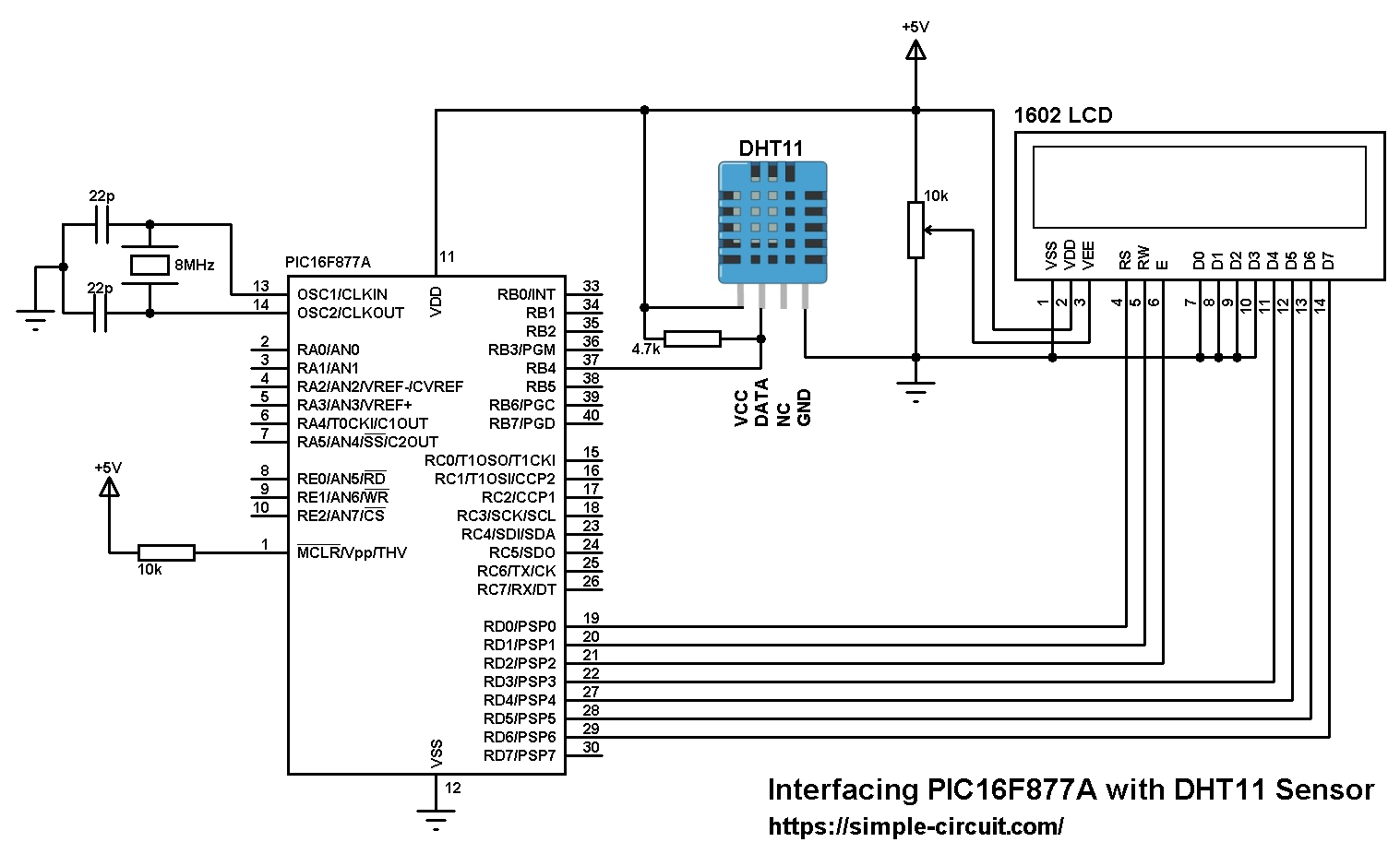
The circuit is simple, there is the microcontroller PIC16F877A, DHT11 sensor and 1602 LCD to display humidity and temperature results.
The DHT11 sensor has 4 pins:
VCC : Positive power supply (+5V)
DATA : Sensor data input and output
NC : Not connected terminal
GND : Ground (0V)
A pull-up resistor must be added between the DHT11 data pin and VCC (+5V) pin as shown in the circuit schematic (4.7K ~ 10K).
Interfacing PIC16F877A with DHT11 humidity and temperature sensor C code:
The interfacing code was tested with CCS PIC C compiler version 5.051.
If you want to understand the code please read the DHT11 datasheet.
Variables Time_out and k are used to test reading time to avoid wrong data reception and microcontroller hanging.
1 2 3 4 5 6 7 8 9 10 11 12 13 14 15 16 17 18 19 20 21 22 23 24 25 26 27 28 29 30 31 32 33 34 35 36 37 38 39 40 41 42 43 44 45 46 47 48 49 50 51 52 53 54 55 56 57 58 59 60 61 62 63 64 65 66 67 68 69 70 71 72 73 74 75 76 77 78 79 80 81 82 83 84 85 86 87 88 89 90 91 92 93 94 95 96 97 98 99 100 101 102 103 104 105 106 107 108 109 110 111 112 113 114 115 116 117 118 119 120 121 122 123 124 125 126 127 | /* * Interfacing PIC16F877A microcontroller with DHT11 temperature * and humidity sensor. * C Code for CCS C compiler. * Temperature, humidity and pressure values are displayed on 20x4 LCD. * This is a free software with NO WARRANTY. * http://simple-circuit.com/ */ // LCD module connections #define LCD_RS_PIN PIN_D0 #define LCD_RW_PIN PIN_D1 #define LCD_ENABLE_PIN PIN_D2 #define LCD_DATA4 PIN_D3 #define LCD_DATA5 PIN_D4 #define LCD_DATA6 PIN_D5 #define LCD_DATA7 PIN_D6 // end LCD module connections #include <16F877A.h> #fuses HS,NOWDT,NOPROTECT,NOLVP #use delay(clock = 8000000) #include <lcd.c> // include LCD driver source file #use fast_io(B) #define DHT11_PIN PIN_B4 // connection pin between DHT11 and mcu char message1[] = "Temp = 00.0 C "; char message2[] = "RH = 00.0 % "; short Time_out; unsigned int8 T_byte1, T_byte2, RH_byte1, RH_byte2, CheckSum ; void start_signal(){ output_drive(DHT11_PIN); // configure connection pin as output output_low(DHT11_PIN); // connection pin output low delay_ms(25); output_high(DHT11_PIN); // connection pin output high delay_us(30); output_float(DHT11_PIN); // configure connection pin as input } short check_response(){ delay_us(40); if(!input(DHT11_PIN)){ // read and test if connection pin is low delay_us(80); if(input(DHT11_PIN)){ // read and test if connection pin is high delay_us(50); return 1; } } } unsigned int8 Read_Data(){ unsigned int8 i, k, _data = 0; // k is used to count 1 bit reading duration if(Time_out) break; for(i = 0; i < 8; i++){ k = 0; while(!input(DHT11_PIN)){ // Wait until DHT11 pin get raised k++; if(k > 100){ Time_out = 1; break; } delay_us(1); } delay_us(30); if(!input(DHT11_PIN)) bit_clear(_data, (7 - i)); // Clear bit (7 - i) else{ bit_set(_data, (7 - i)); // Set bit (7 - i) while(input(DHT11_PIN)){ // Wait until DHT11 pin goes low k++; if(k > 100){ Time_out = 1; break; } delay_us(1);} } } return _data; } void main(){ lcd_init(); // Initialize LCD module lcd_putc('\f'); // LCD clear delay_ms(1000); while(TRUE){ Time_out = 0; Start_signal(); if(check_response()){ // If there is a response from sensor RH_byte1 = Read_Data(); // read RH byte1 RH_byte2 = Read_Data(); // read RH byte2 T_byte1 = Read_Data(); // read T byte1 T_byte2 = Read_Data(); // read T byte2 Checksum = Read_Data(); // read checksum if(Time_out){ // If reading takes long time lcd_putc('\f'); // LCD clear lcd_gotoxy(5, 1); // Go to column 5 row 1 lcd_putc("Time out!"); } else{ if(CheckSum == ((RH_Byte1 + RH_Byte2 + T_Byte1 + T_Byte2) & 0xFF)){ message1[7] = T_Byte1/10 + 48; message1[8] = T_Byte1%10 + 48; message1[10] = T_Byte2/10 + 48; message2[7] = RH_Byte1/10 + 48; message2[8] = RH_Byte1%10 + 48; message2[10] = RH_Byte2/10 + 48; message1[11] = 223; // Degree symbol lcd_gotoxy(1, 1); // Go to column 1 row 1 printf(lcd_putc, message1); // Display message1 lcd_gotoxy(1, 2); // Go to column 1 row 2 printf(lcd_putc, message2); // Display message2 } else{ lcd_putc('\f'); // LCD clear lcd_gotoxy(1, 1); // Go to column 1 row 1 lcd_putc("Checksum Error!"); } } } else { lcd_putc('\f'); // LCD clear lcd_gotoxy(3, 1); // Go to column 3 row 1 lcd_putc("No response"); lcd_gotoxy(1, 2); // Go to column 1 row 2 lcd_putc("from the sensor"); } delay_ms(1000); } } |
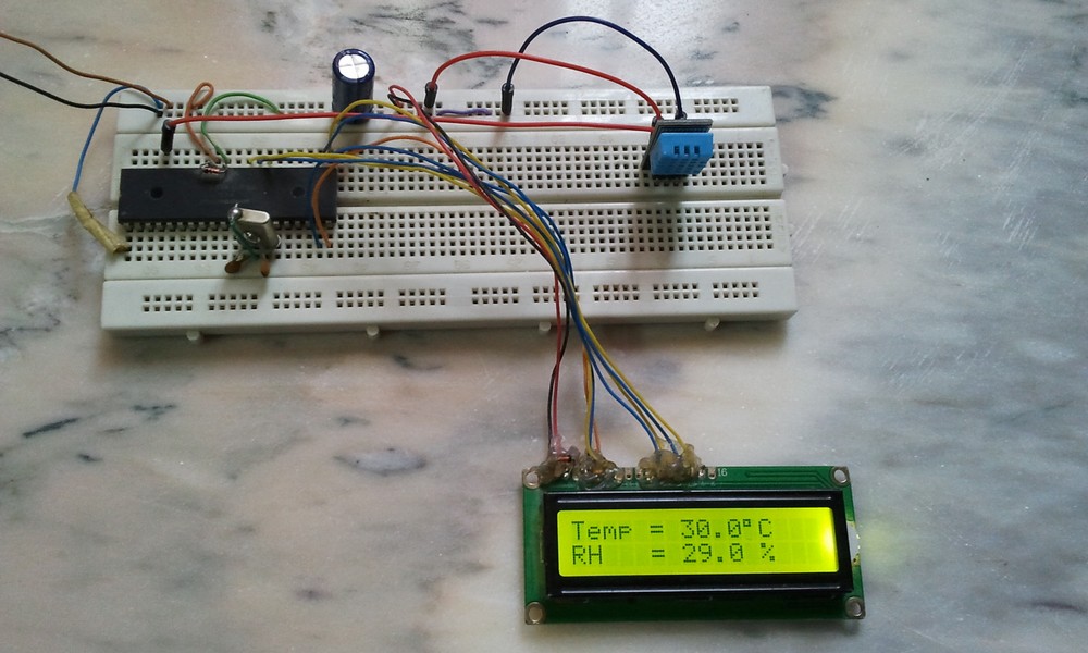
PIC16F877A with DHT11 relative humidity and temperature sensor video:
The following video shows the project circuit connected in a breadboard.

Hello. I receive No response from sensor all the time.What can I do?
double check on your Rock-crystal frequency
Hi, where is lcd source file ? (#include <lcd.c>)
That’s a built-in driver file, it comes with CCS C compiler and there is no need to add it!
Hi… i cannot understand why on the rows 91 to 97 you add +48 to each digit
Data are sent to the LCD in ASCII format and to convert a number to ASCII code we’ve to add 48 to it (for example ASCII code for 2 is: 2 + 48 = 50).