This topic shows how to make a simple infrared (IR) remote control system using the microcontroller PIC12F1822. This IR system has two circuits as known: IR transmitter circuit and IR receiver circuit. Both circuit based on the same microcontroller type which is PIC12F1822.
This IR system uses NEC communication protocol. To see how the NEC protocol works read the following topic which shows how to decode this communication protocol using PIC12F1822 microcontroller.
Extended NEC Protocol Decoder Using PIC12F1822 – CCS C
Components List:
Transmitter Circuit:
- PIC12F1822 Microcontroller
- IR Transmitter
- 2N2222 Transistor
- 5 Push Buttons
- 10k Resistor
- 100Ohm Resistor
- +5V Power Source
- Protoboard
- Jumper Wires
Receiver Circuit:
- PIC12F1822 Microcontroller
- IR Receiver
- 5 LEDs
- 10k Resistor
- 5 x 470 Ohm Resistors
- 47uF Capacitor
- +5V Power Source
- Protoboard
- Jumper Wires
NEC Protocol IR transmitter (Encoder) using PIC12F1822:
The following image shows the IR system transmitter circuit schematic diagram.
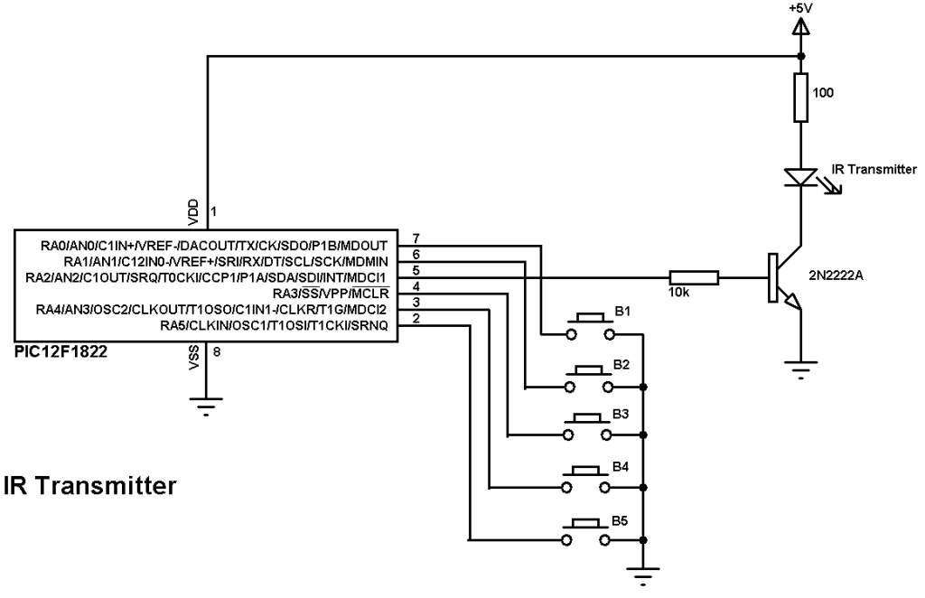
In the circuit there 5 push buttons and each button sends a different IR signal code. The IR transmitter is the element that sends the IR signals to the IR receiver circuit.
The NPN transistor 2N2222 is used to drive the IR transmitter because the IR transmitter consumes high current and the microcontroller generally can’t provide that amount of current.
PIC12F1822 internal pull-ups are enabled by the software and the internal oscillator is used as usual.
NEC Protocol IR transmitter (Encoder) using PIC12F1822 CCS PIC C code:
This is the full code of microcontroller of the NEC IR transmitter.
The NEC protocol carrier frequency is 38KHz and to generate this frequency PIC12F1822 CCP module is used as a PWM module. The flLowing CCS C line is used to configure the PWM module:
#use pwm (PWM1, FREQUENCY = 38KHz, DUTY = 25, PWM_OFF)
The internal oscillator is used and set to 8MHz with PLL enabled (8 x 4 = 32MHz). The following line is used for that:
setup_oscillator(OSC_8MHZ | OSC_PLL_ON);
In the circuit there are 5 push buttons connected to RA0, RA1, RA3, RA4 and RA5 which means that pins must be configured as inputs and the PWM pin as output.
Internal pull-ups are enabled for the input pins with the following line:
port_a_pullups(0x3B);
The five buttons transmit the following signals respectively:
0x40BF00FF — 0x40BF807F — 0x40BF40BF — 0x40BF20DF — 0x40BFA05F
1s and 0s are transmitted as:
Transmit 1 : pwm_on();
Transmit 0: pwm_off();
For example the transmission of 9ms burst pulse and 4.5ms space:
// Send 9ms burst
pwm_on();
delay_ms(9);
// Send 4.5ms space
pwm_off();
delay_us(4500);
Full Code:
1 2 3 4 5 6 7 8 9 10 11 12 13 14 15 16 17 18 19 20 21 22 23 24 25 26 27 28 29 30 31 32 33 34 35 36 37 38 39 40 41 42 43 44 45 46 47 48 49 50 51 52 53 54 55 56 57 58 59 60 61 62 63 64 65 66 67 | // Extended NEC protocol IR remote control transmitter CCS C code #include <12F1822.h> #fuses NOMCLR INTRC_IO PLL_SW #use delay(clock=32000000) #use fast_io(A) #use pwm (PWM1, FREQUENCY = 38KHz, DUTY = 25, PWM_OFF) void send_signal(unsigned int32 number){ int8 i; // Send 9ms burst pwm_on(); delay_ms(9); // Send 4.5ms space pwm_off(); delay_us(4500); // Send data for(i = 0; i < 32; i++){ // If bit is 1 send 560us pulse and 1680us space if(bit_test(number, 31 - i)){ pwm_on(); delay_us(560); pwm_off(); delay_us(1680); } // If bit is 0 send 560us pulse and 560us space else{ pwm_on(); delay_us(560); pwm_off(); delay_us(560); } } // Send end bit pwm_on(); delay_us(560); pwm_off(); delay_us(560); } void main() { setup_oscillator(OSC_8MHZ | OSC_PLL_ON); // Set internal oscillator to 32MHz (8MHz and PLL) output_a(0); set_tris_a(0x3B); // Configure RA2 pin as output and others as inputs port_a_pullups(0x3B); // Enable internal pull-ups for pins RA0,RA1,RA3,RA4 & RA5 while(TRUE){ while(!input(PIN_A0)){ send_signal(0x40BF00FF); delay_ms(500); } while(!input(PIN_A1)){ send_signal(0x40BF807F); delay_ms(500); } while(!input(PIN_A3)){ send_signal(0x40BF40BF); delay_ms(500); } while(!input(PIN_A4)){ send_signal(0x40BF20DF); delay_ms(500); } while(!input(PIN_A5)){ send_signal(0x40BFA05F); delay_ms(500); } } } |
NEC Protocol IR receiver (Decoder) using PIC12F1822:
The NEC receiver circuit schematic is shown below.
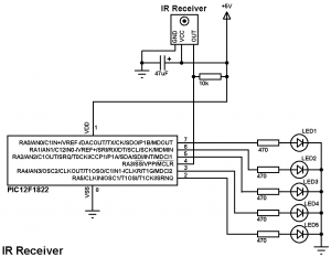
In the IR receiver circuit there are 5 LEDs and IR receiver. The IR receiver receives IR signals transmitted from the IR transmitter. Each LED is remotely controlled from one button in the transmitter circuit.
PIC12F1822 internal oscillator is used and MCLR pin is configured as a digital input pin.
NEC Protocol IR receiver (Decoder) using PIC12F1822 CCS PIC C code:
As in the IR transmitter the internal oscillator of the IR receiver microcontroller is used.
Timer1 is configured to increment every 1us and it is used to measure pulses spaces duration.
SETUP_TIMER_1(T1_INTERNAL | T1_DIV_BY_8);
For example to check the 9ms pulse the following lines are used:
// Check 9ms pulse (remote control sends logic high)
SET_TIMER1(0);
while(!input(IR_Sensor) && (count < 9500))
count = GET_TIMER1();
if( (count > 9499) || (count < 8500))
return FALSE;
And checking the 4.5ms space as follows:
// Check 4.5ms space (remote control sends logic low)
SET_TIMER1(0);
count = 0;
while((input(IR_Sensor)) && (count < 5000))
count = GET_TIMER1();
if( (count > 4999) || (count < 4000))
return FALSE;
Full Code:
1 2 3 4 5 6 7 8 9 10 11 12 13 14 15 16 17 18 19 20 21 22 23 24 25 26 27 28 29 30 31 32 33 34 35 36 37 38 39 40 41 42 43 44 45 46 47 48 49 50 51 52 53 54 55 56 57 58 59 60 61 62 63 64 65 66 67 | // Extended NEC protocol IR remote control decoder using PIC12F1822 CCS C code #include <12F1822.h> #fuses NOMCLR INTRC_IO PLL_SW #use delay(clock=32000000) #use fast_io(A) #define IR_Sensor PIN_A3 unsigned int32 ir_code; short nec_remote_read(){ unsigned int16 count = 0; unsigned int8 i; // Check 9ms pulse (remote control sends logic high) SET_TIMER1(0); while(!input(IR_Sensor) && (count < 9500)) count = GET_TIMER1(); if( (count > 9499) || (count < 8500)) return FALSE; // Check 4.5ms space (remote control sends logic low) SET_TIMER1(0); count = 0; while((input(IR_Sensor)) && (count < 5000)) count = GET_TIMER1(); if( (count > 4999) || (count < 4000)) return FALSE; // Read message (32 bits) for(i = 0; i < 32; i++){ SET_TIMER1(0); count = 0; while(!input(IR_Sensor) && (count < 650)) count = GET_TIMER1(); if( (count > 649) || (count < 500)) return FALSE; count = 0; SET_TIMER1(0); while((input(IR_Sensor)) && (count < 1800)) count = GET_TIMER1(); if( (count > 1799) || (count < 400)) return FALSE; if( count > 1000) // If space width > 1ms bit_set(ir_code, (31 - i)); // Write 1 to bit (31 - i) else // If space width < 1ms bit_clear(ir_code, (31 - i)); // Write 0 to bit (31 - i) } return TRUE; } void main() { setup_oscillator(OSC_8MHZ | OSC_PLL_ON); // Set internal oscillator to 32MHz (8MHz and PLL) output_a(0); set_tris_a(8); SETUP_TIMER_1(T1_INTERNAL | T1_DIV_BY_8); while(TRUE){ while(input(IR_Sensor)); // Wait until IR_Sensor pin falls if(nec_remote_read()){ if(ir_code == 0x40BF00FF) output_toggle(PIN_A0); if(ir_code == 0x40BF807F) output_toggle(PIN_A1); if(ir_code == 0x40BF40BF) output_toggle(PIN_A2); if(ir_code == 0x40BF20DF) output_toggle(PIN_A4); if(ir_code == 0x40BFA05F) output_toggle(PIN_A5); } } } |
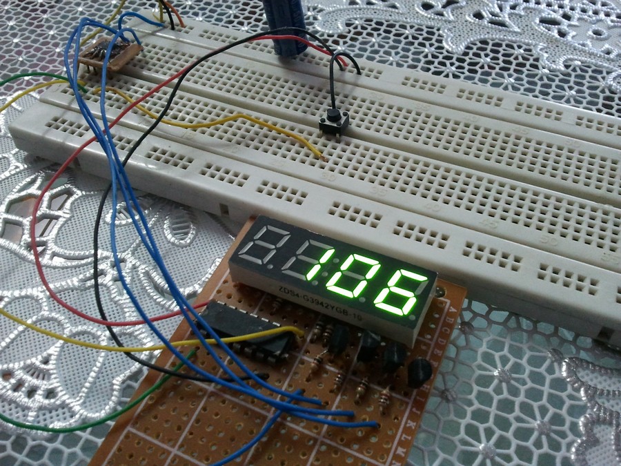
IR Remote control transmitter and receiver using PIC12F1822 microcontroller video:
The following video shows project final result.
please help me, how do I port the code of the transmitter and receiver to pic 10F322 ? This pic has no 16-bit timer1, only 8-bit timer0 and timer2. would it be possible for you to help me?
I’m using CCS C v5.103 and I’m having problems getting the receiver to respond to remote commands, the code compiled just fine, but I’m not sure if it’s being compiled correctly, thanks for any responses.