This topic shows how to build a temperature and humidity data logger using PIC18F46K22 microcontroller, SD card and DHT22 (AM2302) digital humidity and temperature sensor.
The PIC18F46K22 MCU reads temperature (in °C) and humidity (in %rH) values from the DHT22 sensor and saves them to a text file stored in the SD card. DS3231 real time clock chip is used to get time and date information.
Time, date, temperature and humidity values are displayed on 20×4 LCD screen.
MikroC PRO for PIC compiler is used in this project.
FAT32 Library for mikroC compiler:
MikroElektronika provides a nice library for FAT32 file system (& SD card). This library can be downloaded from the following link:
FAT32 Library for mikroC compiler
The extension of the downloaded file is .mpkg, and in order to open and install the library we need a small software named: Package Manager, it’s also a free software provided by MikroElektronika, download link is below:
Package Manager download
To see how to interface PIC18F46K22 with SD card, visit the following post:
PIC18F46K22 Interface with SD card – Write & read files | mikroC Projects
Hardware Required:
This is a list of all components required to build this project.
- PIC18F46K22 microcontroller —-> datasheet
- FAT32 formatted SD card (MMC, SD, SDHC, microSD ….)
- micro SD card module
- USB-to-serial UART converter (like: FT232RL module)
- 20×4 LCD screen
- DHT22 sensor (AM2302, RHT03 …) —-> DHT22 datasheet
- DS3231 board —-> DS3231 datasheet
- 4.7k ohm resistor
- 330 ohm resistor
- 2 x push button
- 10k ohm variable resistor or potentiometer
- 3V coin cell battery
- Breadboard
- 5V source
- Jumper wires
Temperature and humidity data logger using PIC18F46K22 circuit:
The following image shows project hardware circuit diagram.
As a small hint, it’s highly recommended to add a voltage level translator to MISO line in order to step up the 3.3V that comes from the SD card into 5V which goes to SDI1 pin (#23) of the PIC18F46K22 microcontroller, here we can use the integrated circuit 74HCT125.
In this project I used micro SD card module, this module is supplied from circuit 5V source, it contains the AMS1117-3V3 voltage regulator which is used to supply the SD card with 3.3V. Also this module contains an IC which is 74LVC125A and it is used as level translator (from 5V to 3.3V).
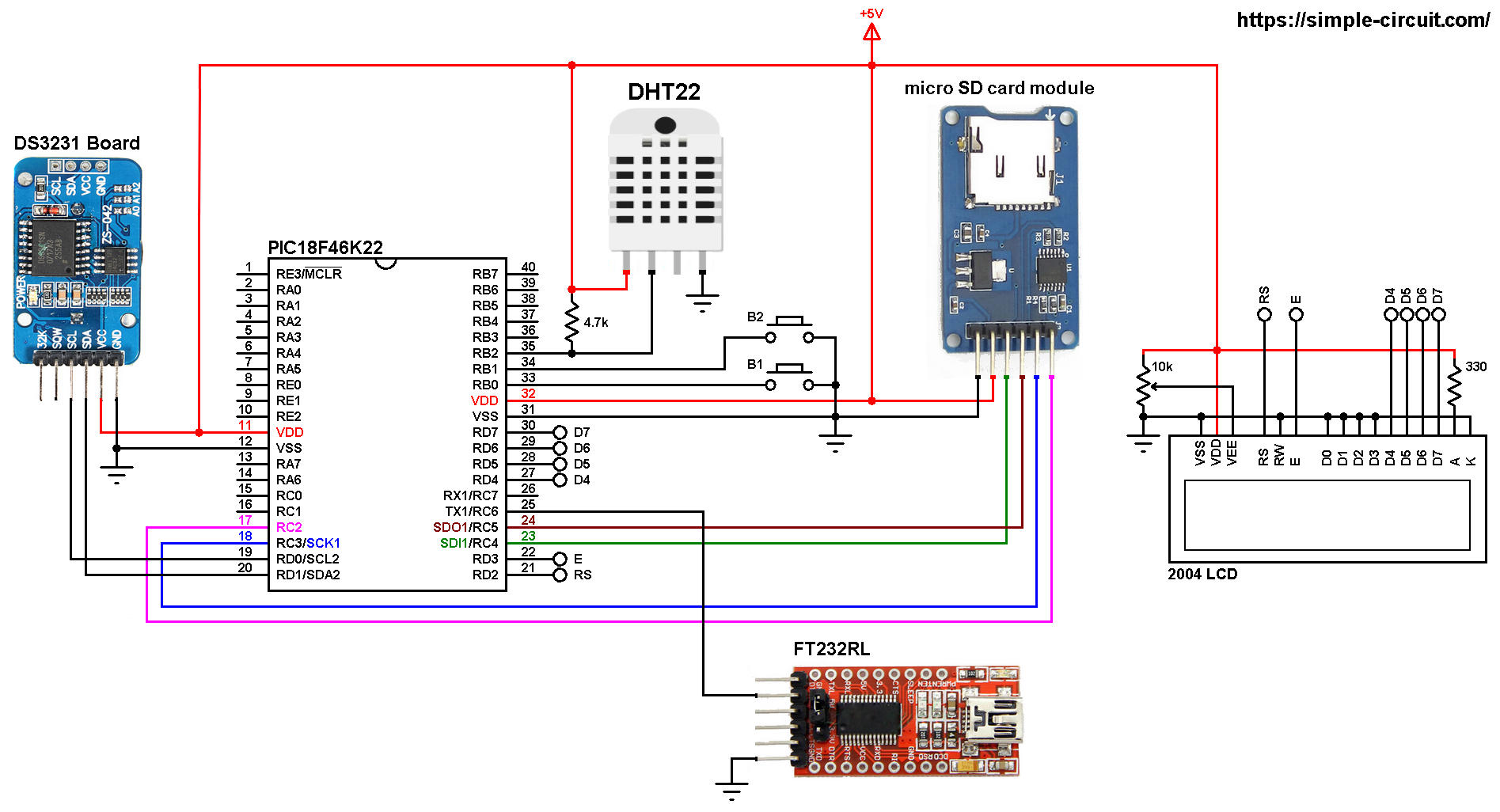
All the grounded terminals are connected together.
The PIC18F46K22 microcontroller does have 2 MSSP modules: MSSP1 and MSSP2 (MSSP: Master Synchronous Serial Port), each one of them may work as hardware SPI module or hardware I2C module. The SD card uses SPI protocol, it’s connected to MSSP1 module (used as SPI) hardware pins (SCK1, SDI1 and SDO1). So the micro SD card module is connected to the circuit as follows (from left to right):
The first pin of the micro SD card module (GND) is connected to circuit ground.
The second pin of the micro SD card module (VCC) is connected to circuit +5V.
The third pin of the micro SD card module (MISO) is connected to pin SDI1 (RC4) of the PIC18F46K22.
The fourth pin of the micro SD card module (MOSI) is connected to pin SDO1 (RC5) of the PIC18F46K22.
The fifth pin of the micro SD card module (SCK) is connected to pin SCK1 (RC3) of the PIC18F46K22.
The last pin of the micro SD card module (CS) is connected to pin RC2 of the PIC18F46K22.
The DS3231 RTC chip uses I2C protocol, its board data pins (SCL and SDA) are connected to MSSP2 module which is configured to operate in I2C mode. So, the SCL and SDA pins of the DS3231 board are respectively connected to SCL2 (RD0) and SDA2 (RD1) of the PIC18F46K22 microcontroller.
In the circuit there are two push buttons: B1 and B2, they are connected to pins RB0 (#33) and RB1 (#34) respectively, these buttons are used to set time and date of the real time clock.
The DHT22 sensor has 4 pins (from left to right): VCC, data, not connected pin and GND where:
VCC is connected to +5V
Data pin is connected to pin RB2 (#35) of the PIC18F46K22
GND is connected to circuit ground (0V).
The 20×4 LCD screen (4 rows and 20 columns) is used to display time, date, humidity and temperature where:
RS —> pin RD2
E —> pin RD3
D4 —> pin RD4
D5 —> pin RD5
D6 —> pin RD6
D7 —> pin RD7
VSS, RW, D0, D1, D2, D3 and K are connected to circuit ground
VEE to the variable resistor (or potentiometer) output
VDD to +5V and A to +5V through 330 ohm resistor.
VEE pin is used to control the contrast of the LCD. A (anode) and K (cathode) are the back light LED pins.
The FT232RL board (USB to serial converter) RX pin is connected to PIC18F46K22 TX1 pin (RC6) which is USART1 module transmission pin (the PIC18F46K22 has 2 hardware USART modules). This board is used just to send some data from the microcontroller to PC.
In this project the PIC18F46K22 microcontroller runs with its internal oscillator @ 16 MHz and MCLR pin is configured as input.
Temperature data logger using PIC18F46K22 C code:
The C code below is for mikroC PRO for PIC compiler, it was tested with version 7.2.0.
To be able to compile project C code with no error, a driver (library) for the DS3231 RTC is required, download link is below. After you download the driver file which named DS3231.c, add it to your project folder.
DS3231 mikroC library
For more details about the DS1307 library, visit the following post:
DS3231 RTC Library for mikroC Compiler | mikroC Projects
The SD card chip select pin (SS) is connected to pin RC2 of the PIC18F46K22, it’s defined in the C code as:
1 2 3 | // SD card chip select pin connection sbit Mmc_Chip_Select at RC2_bit; sbit Mmc_Chip_Select_Direction at TRISC2_bit; |
The connection of the two push buttons are defined in the code as shown below:
1 2 3 | // button definitions #define button1 RB0_bit // button B1 is connected to RB0 pin #define button2 RB1_bit // button B2 is connected to RB1 pin |
The microcontroller reads temperature & humidity values from the DHT22 sensor and saves them (with time and date) to the SD card every second, for that I used the following if condition:
1 | if( mytime->seconds != p_second ) |
where the variable p_second is used to save only one value every 1 second.
Functions used in the code:
FAT32_Init(): this function initializes the FAT32 library as well as the SD card, it returns 0 if OK and non-zero if error.
FAT32_Exists(“DHT22Log.txt”): search if there is a file named “DHT22Log.txt” exists in the selected directory, return 0 if the file isn’t present, otherwise it returns a non-zero value (for example the file exists).
FAT32_Open(“DHT22Log.txt”, FILE_WRITE): this function creates a new file named “DHT22Log.txt”, returns 0 if OK and non-zero if error.
FAT32_Open(“DHT22Log.txt”, FILE_APPEND): this function opens the file named “DHT22Log.txt” and moves the cursor to the end of the file, returns 0 if OK and non-zero if error.
FAT32_Write(fileHandle, “…”, 26): writes a text (for example “…” ) of length (for example 26 characters) to the file associated with fileHandler.
FAT32_Close(fileHandle): closes the file associated with fileHandler, returns 0 if OK and non-zero if error.
char debounce (): this function is for button B1 debounce, returns 1 if button is debounced.
void wait(): this function is just a delay of 500 ms except that it can be interrupted by the two push buttons (B1 and B2). In this function Timer0 module is used to count the 500 milliseconds, it is used as 16-bit timer with prescaler = 32 (==> 1 tick every 8 microseconds ==> 62500 x 8 = 500000 us = 500 ms).
char edit(char x_pos, char y_pos, char parameter): this function is for setting the real time clock, returns the edited parameter.
void dow_print(): displays day of the week (Monday, Tuesday …) on the LCD.
void rtc_print(): displays time and date on the LCD. This function calls the previous one for displaying day of the week.
void Start_Signal(void): sends start signal to the DHT22 sensor.
char Check_Response(): checks response signal of the DHT22 sensor (after sending the start signal using the previous function), returns 1 if OK and 0 if error.
void Read_Data(unsigned short* dht_data): reads 1 byte from the DHT22 sensor which is saved to the variable dht_data.
Time, date, temperature and humidity are displayed on 20×4 LCD.
If there is a problem with the DHT22 sensor (for example bad connection) the LCD will display Sensor (on the 3rd row) Error (on the 4th row), and if there is a check sum error (for example due to wrong data reading) the LCD will display Checksum (on the 3rd row) Error (on the 4th row).
These errors will be also printed to the “DHT22Log.txt” file instead of temperature and humidity values.
Rest of code is described through comments.
Full mikroC code:
1 2 3 4 5 6 7 8 9 10 11 12 13 14 15 16 17 18 19 20 21 22 23 24 25 26 27 28 29 30 31 32 33 34 35 36 37 38 39 40 41 42 43 44 45 46 47 48 49 50 51 52 53 54 55 56 57 58 59 60 61 62 63 64 65 66 67 68 69 70 71 72 73 74 75 76 77 78 79 80 81 82 83 84 85 86 87 88 89 90 91 92 93 94 95 96 97 98 99 100 101 102 103 104 105 106 107 108 109 110 111 112 113 114 115 116 117 118 119 120 121 122 123 124 125 126 127 128 129 130 131 132 133 134 135 136 137 138 139 140 141 142 143 144 145 146 147 148 149 150 151 152 153 154 155 156 157 158 159 160 161 162 163 164 165 166 167 168 169 170 171 172 173 174 175 176 177 178 179 180 181 182 183 184 185 186 187 188 189 190 191 192 193 194 195 196 197 198 199 200 201 202 203 204 205 206 207 208 209 210 211 212 213 214 215 216 217 218 219 220 221 222 223 224 225 226 227 228 229 230 231 232 233 234 235 236 237 238 239 240 241 242 243 244 245 246 247 248 249 250 251 252 253 254 255 256 257 258 259 260 261 262 263 264 265 266 267 268 269 270 271 272 273 274 275 276 277 278 279 280 281 282 283 284 285 286 287 288 289 290 291 292 293 294 295 296 297 298 299 300 301 302 303 304 305 306 307 308 309 310 311 312 313 314 315 316 317 318 319 320 321 322 323 324 325 326 327 328 329 330 331 332 333 334 335 336 337 338 339 340 341 342 343 344 345 346 347 348 349 350 351 352 353 354 355 356 357 358 359 360 361 362 363 364 365 366 367 368 369 370 371 372 373 374 375 376 377 378 379 380 381 382 383 384 385 386 387 388 389 390 391 392 393 394 395 396 397 398 399 400 401 402 403 404 405 406 407 408 409 410 411 412 413 414 415 | /************************************************************************************** Temperature and humidity data logger using PIC18F46K22 microcontroller, DHT22 sensor and DS3231 RTC. Time, date, temperature and relative humidity are displayed on 20x4 LCD. C Code for mikroC PRO for PIC compiler. Internal oscillator used @ 16MHz Configuration words: CONFIG1H = 0x0028 CONFIG2L = 0x0018 CONFIG2H = 0x003C CONFIG3H = 0x0037 CONFIG4L = 0x0081 CONFIG5L = 0x000F CONFIG5H = 0x00C0 CONFIG6L = 0x000F CONFIG6H = 0x00E0 CONFIG7L = 0x000F CONFIG7H = 0x0040 This is a free software with NO WARRANTY. http://simple-circuit.com/ ***************************************************************************************/ // SD card chip select pin connection sbit Mmc_Chip_Select at RC2_bit; sbit Mmc_Chip_Select_Direction at TRISC2_bit; // DHT22 sensor connection (here data pin is connected to pin RB2) #define DHT22_PIN RB2_bit #define DHT22_PIN_DIR TRISB2_bit // LCD module connections sbit LCD_RS at RD2_bit; sbit LCD_EN at RD3_bit; sbit LCD_D4 at RD4_bit; sbit LCD_D5 at RD5_bit; sbit LCD_D6 at RD6_bit; sbit LCD_D7 at RD7_bit; sbit LCD_RS_Direction at TRISD2_bit; sbit LCD_EN_Direction at TRISD3_bit; sbit LCD_D4_Direction at TRISD4_bit; sbit LCD_D5_Direction at TRISD5_bit; sbit LCD_D6_Direction at TRISD6_bit; sbit LCD_D7_Direction at TRISD7_bit; // end LCD module connections // button definitions #define button1 RB0_bit // button B1 is connected to RB0 pin #define button2 RB1_bit // button B2 is connected to RB1 pin #define DS3231_I2C2 // use hardware I2C2 moodule (MSSP2) for DS3231 RTC #include <DS3231.c> // include DS3231 RTC driver source file RTC_Time *mytime; // DS3231 library variable // include __Lib_FAT32.h file (useful definitions) #include "__Lib_FAT32.h" __HANDLE fileHandle; // only one file can be opened // other variable short fat_err; short i, p_second = 1; // a small function for button1 (B1) debounce char debounce() { char m, count = 0; for(m = 0; m < 5; m++) { if ( !button1 ) count++; delay_ms(10); } if(count > 2) return 1; else return 0; } // interrupted delay void wait() { unsigned int TMR0_value = 0; TMR0L = TMR0H = 0; // rest Timer0 low and high registers while( (TMR0_value < 62500L) && button1 && button2 ) TMR0_value = (TMR0H << 8) | TMR0L; } char edit(char x_pos, char y_pos, char parameter) { char buffer[3]; while(debounce()); // call debounce function (wait for B1 to be released) sprinti(buffer, "%02u", (int)parameter); while(1) { while( !button2 ) { parameter++; if(i == 0 && parameter > 23) // if hours > 23 ==> hours = 0 parameter = 0; if(i == 1 && parameter > 59) // if minutes > 59 ==> minutes = 0 parameter = 0; if(i == 2 && parameter > 31) // if day > 31 ==> day = 1 parameter = 1; if(i == 3 && parameter > 12) // if month > 12 ==> month = 1 parameter = 1; if(i == 4 && parameter > 99) // if year > 99 ==> year = 0 parameter = 0; sprinti(buffer, "%02u", (int)parameter); LCD_Out(y_pos, x_pos, buffer); delay_ms(200); } LCD_Out(y_pos, x_pos, " "); wait(); LCD_Out(y_pos, x_pos, buffer); wait(); if(!button1) // if button B1 is pressed { i++; // increment 'i' for the next parameter return parameter; // return parameter value and exit } } } void dow_print() { switch(mytime->dow) { case SUNDAY : LCD_Out(2, 7, "SUN"); break; case MONDAY : LCD_Out(2, 7, "MON"); break; case TUESDAY : LCD_Out(2, 7, "TUE"); break; case WEDNESDAY: LCD_Out(2, 7, "WED"); break; case THURSDAY : LCD_Out(2, 7, "THU"); break; case FRIDAY : LCD_Out(2, 7, "FRI"); break; default : LCD_Out(2, 7, "SAT"); } } void rtc_print() { char buffer[17]; // print day of the week dow_print(); // print time sprinti(buffer, "%02u:%02u:%02u", (int)mytime->hours, (int)mytime->minutes, (int)mytime->seconds); LCD_Out(1, 11, buffer); // print date sprinti(buffer, "-%02u-%02u-20%02u", (int)mytime->day, (int)mytime->month, (int)mytime->year); LCD_Out(2, 10, buffer); } //////////////////////////////////////// DHT22 functions //////////////////////////////////////// // send start signal to the sensor void Start_Signal(void) { DHT22_PIN = 0; // connection pin output low DHT22_PIN_DIR = 0; // configure connection pin as output delay_ms(25); // wait 25 ms DHT22_PIN = 1; // connection pin output high delay_us(30); // wait 30 us DHT22_PIN_DIR = 1; // configure connection pin as input } // check sensor response char Check_Response() { TMR0L = TMR0H = 0; // rest Timer0 low and high registers // wait until DHT22_PIN becomes high (checking of 80µs low time response) while(!DHT22_PIN && TMR0L < 100) ; if(TMR0L >= 100) // if response time > 80µS ==> response error return 0; // return 0 (device has a problem with response) TMR0L = TMR0H = 0; // rest Timer0 low and high registers // wait until DHT22_PIN becomes low (checking of 80µs high time response) while(DHT22_PIN && TMR0L < 100) ; if(TMR0L >= 100) // if response time > 80µS ==> response error return 0; // return 0 (device has a problem with response) return 1; // return 1 (response OK) } // data read function void Read_Data(unsigned short* dht_data) { *dht_data = 0; for(i = 0; i < 8; i++) { TMR0L = TMR0H = 0; // rest Timer0 low and high registers while(!DHT22_PIN) // wait until DHT22_PIN becomes high { if(TMR0L > 80) // if low time > 80uS ==> Time out error (Normally it takes 50µs) return; // return (timeout error) } TMR0L = TMR0H = 0; // rest Timer0 low and high registers while(DHT22_PIN) // wait until DHT22_PIN becomes low { if(TMR0L > 80) // if high time > 80uS ==> Time out error (normally it takes 26-28µs for 0 and 70µs for 1) return; // return (timeout error) } if(TMR0L > 40) // if high time > 40uS ==> sensor sent 1 *dht_data |= (1 << (7 - i)); // set bit (7 - i) } return; // return (data read OK) } ///////////////////////////////////// end DHT22 functions ////////////////////////////////////// // main function void main() { OSCCON = 0x70; // set internal oscillator to 16MHz ANSELB = 0; // configure all PORTB pins as digital ANSELC = 0; // configure all PORTC pins as digital ANSELD = 0; // configure all PORTD pins as digital // enable RB0 and RB1 internal pull ups RBPU_bit = 0; // clear RBPU bit (INTCON2.7) WPUB = 0x03; // WPUB register = 0b00000011 delay_ms(1000); // wait a second Lcd_Init(); // initialize LCD module Lcd_Cmd(_LCD_CURSOR_OFF); // cursor off Lcd_Cmd(_LCD_CLEAR); // clear LCD LCD_Out(1, 1, "TIME:"); LCD_Out(2, 1, "DATE:"); LCD_Out(3, 1, "TEMP:"); LCD_Out(4, 1, "HUMI:"); // initialize I2C2 module with clock frequency of 100KHz I2C2_Init(100000); // initialize SPI1 module at lowest speed SPI1_Init_Advanced(_SPI_MASTER_OSC_DIV64, _SPI_DATA_SAMPLE_MIDDLE, _SPI_CLK_IDLE_LOW, _SPI_LOW_2_HIGH); UART1_Init(9600); // initialize UART1 module at 9600 baud UART1_Write_Text("\r\n\nInitialize FAT library ... "); fat_err = FAT32_Init(); if(fat_err != 0) { // if there was a problem while initializing the FAT32 library UART1_Write_Text("Error initializing FAT library!"); } else { // the FAT32 library (& SD card) was (were) initialized // re-initialize SPI1 module at highest speed SPI1_Init_Advanced(_SPI_MASTER_OSC_DIV4, _SPI_DATA_SAMPLE_MIDDLE, _SPI_CLK_IDLE_LOW, _SPI_LOW_2_HIGH); UART1_Write_Text("FAT Library initialized"); if(FAT32_Exists("DHT22Log.txt") == 0) // test if file with name 'DHT22.Log.txt' exists { // create a text file named 'DHT22Log.txt' UART1_Write_Text("\r\n\r\nCreate 'DHT22Log.txt' file ... "); fileHandle = FAT32_Open("DHT22Log.txt", FILE_WRITE); if(fileHandle == 0){ UART1_Write_Text("OK"); // write some texts to 'DHT22Log.txt' file FAT32_Write(fileHandle, " DATE | TIME | TEMPERATURE | HUMIDITY\r\n", 49); FAT32_Write(fileHandle, "(dd-mm-yyyy)|(hh:mm:ss)| |\r\n", 40); FAT32_Write(fileHandle, " | | |\r\n", 40); // now close the file 'DHT22Log.txt' FAT32_Close(fileHandle); } else UART1_Write_Text("error creating file."); } } while(1) { // read current time and date from the RTC chip mytime = RTC_Get(); // print all RTC data rtc_print(); if( !button1 ) // if button B1 is pressed if( debounce() ) // call debounce function (make sure if B1 is pressed) { i = 0; while( debounce() ); // call debounce function (wait for button B1 to be released) T0CON = 0x84; // enable Timer0 module (16-bit timer & prescaler = 32) mytime->hours = edit(11, 1, mytime->hours); // edit hours mytime->minutes = edit(14, 1, mytime->minutes); // edit minutes mytime->seconds = 0; // reset seconds while(debounce()); // call debounce function (wait for B1 to be released) while(1) { while( !button2 ) // if button B2 button is pressed { mytime->dow++; if(mytime->dow > SATURDAY) mytime->dow = SUNDAY; dow_print(); // print week day delay_ms(500); // wait half a second } LCD_Out(2, 7, " "); wait(); // call wait() function dow_print(); // print week day wait(); // call wait() function if( !button1 ) // if button B1 is pressed break; } mytime->day = edit(11, 2, mytime->day); // edit day (day of month) mytime->month = edit(14, 2, mytime->month); // edit month mytime->year = edit(19, 2, mytime->year); // edit year TMR0ON_bit = 0; // disable Timer0 module while(debounce()); // call debounce function (wait for button B1 to be released) // write data to the RTC chip RTC_Set(mytime); } // end 'if( debounce() )' if( mytime->seconds != p_second ) { // read & print temperature value from sensor every 1 second char T_Byte1, T_Byte2, RH_Byte1, RH_Byte2, CheckSum; unsigned int Temp, Humi; char temp_a[9], humi_a[8]; bit read_ok; p_second = mytime->seconds; // save current second T0CON = 0x81; // enable Timer0 module (16-bit timer & prescaler = 4) Start_Signal(); // send a start signal to the sensor if(Check_Response()) // check if there is a response from sensor (if OK start reading humidity and temperature data) { // response OK ==> read (and save) data from the DHT22 sensor Read_Data(&RH_Byte1); // read humidity 1st byte and store its value to RH_Byte1 Read_Data(&RH_Byte2); // read humidity 2nd byte and store its value to H_Byte2 Read_Data(&T_Byte1); // read temperature 1st byte and store its value to T_Byte1 Read_Data(&T_Byte2); // read temperature 2nd byte and store its value to T_Byte2 Read_Data(&CheckSum); // read checksum and store its value to CheckSum // test if all data were sent correctly if(CheckSum == ((RH_Byte1 + RH_Byte2 + T_Byte1 + T_Byte2) & 0xFF)) { read_ok = 1; Humi = (RH_Byte1 << 8) | RH_Byte2; Temp = (T_Byte1 << 8) | T_Byte2; if(Temp & 0x8000) { // if temperature is negative Temp = Temp & 0x7FFF; sprinti(temp_a, "-%02u.%01u%cC ", (Temp/10)%100, Temp % 10, (int)223); } else // otherwise (temperature is positive) sprinti(temp_a, " %02u.%01u%cC ", (Temp/10)%100, Temp % 10, (int)223); if(humi >= 1000) // if humidity >= 100.0 rH% sprinti(humi_a, "1%02u.%01u %%", (humi/10)%100, humi % 10); else sprinti(humi_a, " %02u.%01u %%", (humi/10)%100, humi % 10); } else { read_ok = 0; sprinti(temp_a, "Checksum"); sprinti(humi_a, " Error "); } } else { read_ok = 0; sprinti(temp_a, " Sensor "); sprinti(humi_a, " Error "); } TMR0ON_bit = 0; // disable Timer0 module // print sensor data on the LCD LCD_Out(3, 7, temp_a); LCD_Out(4, 7, humi_a); // save sensor data to SD card (DHT22Log.txt file) if(fat_err == 0) { // if the FAT32 library was successfully initialized char buffer[28]; sprinti(buffer, " %02u-%02u-20%02u | %02u:%02u:%02u | ", (int)mytime->day, (int)mytime->month, (int)mytime->year, (int)mytime->hours, (int)mytime->minutes, (int)mytime->seconds); // open 'DHT22Log.txt' file with append permission fileHandle = FAT32_Open("DHT22Log.txt", FILE_APPEND); if(fileHandle == 0) { FAT32_Write(fileHandle, buffer, 27); if(read_ok == 1) // if there's no checksum or sensor error temp_a[5] = '°'; // put degree symbol FAT32_Write(fileHandle, temp_a, 8); FAT32_Write(fileHandle, " | ", 5); FAT32_Write(fileHandle, humi_a, 7); FAT32_Write(fileHandle, "\r\n", 2); // start a new line // now close the file (DHT22Log.txt) FAT32_Close(fileHandle); } } // end 'if(fat_err == 0)' } // end 'if( mytime->seconds != p_second )' delay_ms(100); // wait 100 milliseconds } // end 'while(1)' } // end main function // end of code. |
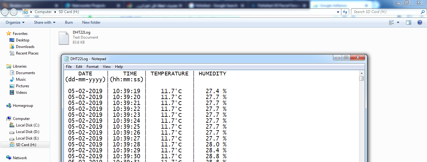
This project was tested in real hardware circuit using original Samsung microSD card with capacity of 32GB. The following image shows a part from the logger file (DHT22Log.txt) created by the hardware circuit:
Proteus simulation:
This project could be simulated using Proteus software, the following video shows the result of the simulation.
Note that Proteus simulation circuit is not the same as real hardware circuit, project hardware circuit is shown above.
Proteus simulation file download link:
PIC18F46k22 SD card DS3231 DHT22 datalogger
SD Card image file (FAT32_MBR.ima) download link:
SD Card FAT32 image