This PIC16F887 project shows how to read analog voltages from analog channel and print the correspondent digital values on a multiplexed 4-digit 7-segment display. A potentiometer is used to get a voltage that varies between 0 and 5V. A common anode 7-segment display is used in this example.
The compiler used in this project is the MikroElektronika mikroC PRO for PIC.
What makes this project so easy is that the PIC16F887 microcontroller already has a 10-bit ADC module with total analog channels of 14.
Last time I made a simple interfacing of PIC16F887 microcontroller with 7-segment display, project link is below:
Interfacing PIC microcontroller with 7-segment display | mikroC Projects
Components Required:
- PIC16F887 microcontroller —-> datasheet
- 4-digit common anode 7-segment display
- 4 x PNP transistor (2SA1015, 2S9015, 2N3906 …)
- 10k ohm potentiometer
- 7 x 100 ohm resistor
- 4 x 4.7k ohm resistor
- 5V source
- Breadboard
- Jumper wires
- PIC MCU Programmer (PICkit 3, PICkit 4…)
Print ADC values on 7-segment display with PIC16F887 circuit:
The following image shows example circuit diagram.
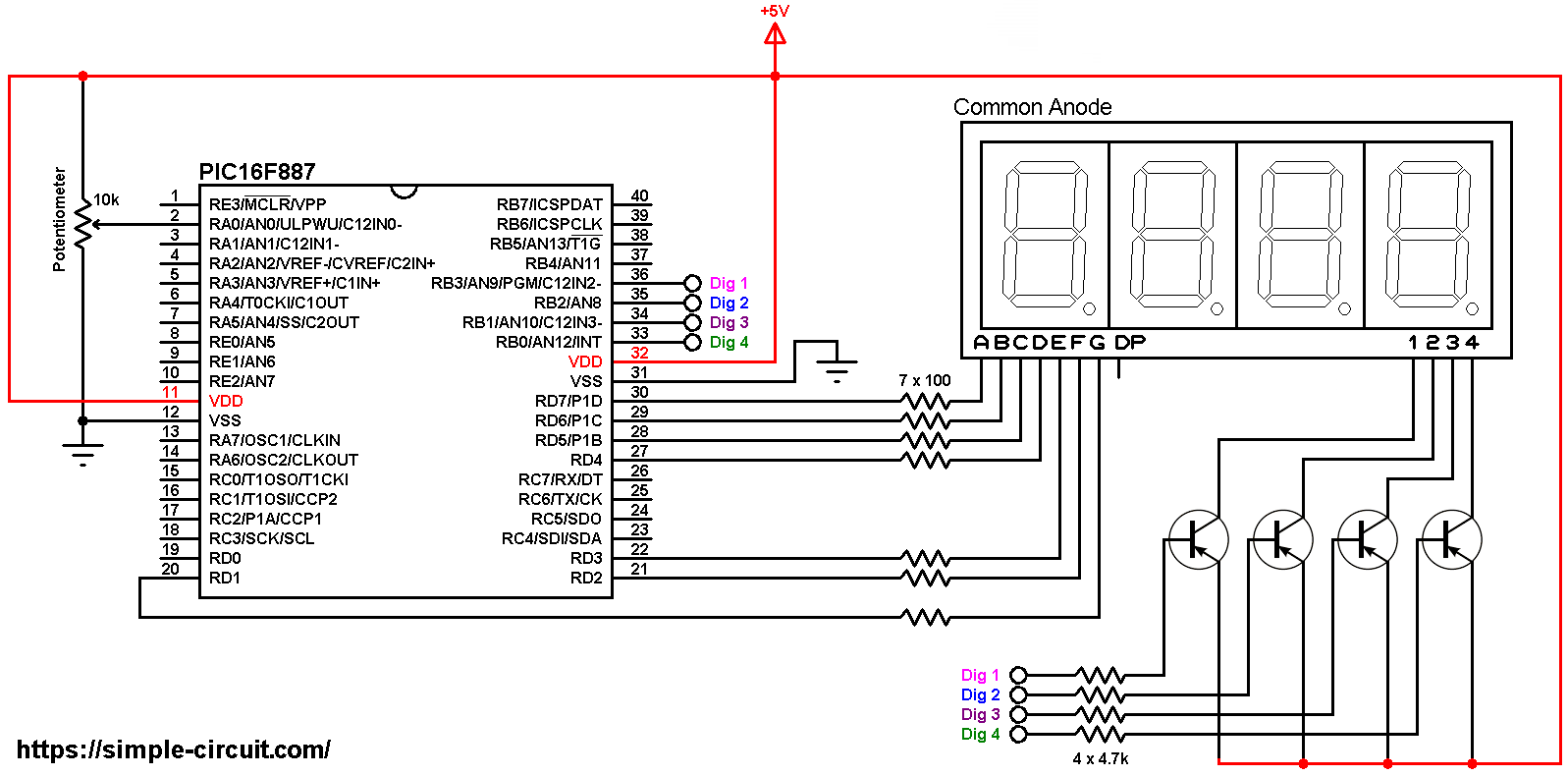
All the grounded terminal are connected together.
The four transistors used in this example are of the same type (PNP).
The potentiometer has 3 pins VCC , output and GND where:
VCC is connected to +5V
The output pin is connected to PIC16F887 analog channel 0 (AN0)
GND is connected to circuit ground.
In this project the PIC16F887 microcontroller runs with its internal oscillator @ 8 MHz, MCLR pin is configured as an input pin.
The Code:
The following C code is for mikroC PRO for PIC compiler, it was tested with version 7.2.0.
Since the 4 digits are multiplexed we need to refresh the display very quickly (display one digit at a time, others are off), for that I used Timer0 module (8-bit timer) interrupt with 1:16 prescaler, this means Timer0 overflows every 2048 microseconds { 256/[8/(4 x 16)] = 256 x 8 = 2048 microseconds }.
The PIC16F887 ADC (Analog-to-Digital Converter) reads analog voltage applied to analog channel AN0 (#2) and convert it to a digital representation which is then printed on the 7-segment display.
The PIC16F887 microcontroller has a built-in ADC module with 10-bit resolution. With a positive reference voltage of VCC (+5V) a 0V is represented by 0 and 5V is represented by 1023.
Full mikroC code:
Configuration words:
CONFIG1 = 0x2CD4
CONFIG2 = 0x0700
1 2 3 4 5 6 7 8 9 10 11 12 13 14 15 16 17 18 19 20 21 22 23 24 25 26 27 28 29 30 31 32 33 34 35 36 37 38 39 40 41 42 43 44 45 46 47 48 49 50 51 52 53 54 55 56 57 58 59 60 61 62 63 64 65 66 67 68 69 70 71 72 73 74 75 76 77 78 79 80 81 82 83 84 85 86 87 88 89 90 91 92 93 94 95 96 97 98 99 | /************************************************************************************** Interfacing PIC16F887 with common anode 7-segment display. Print ADC values on 4-digit 7-segment display. C Code for mikroC PRO for PIC compiler. Internal oscillator used @ 8MHz Configuration words: CONFIG1 = 0x2CD4 CONFIG2 = 0x0700 This is a free software with NO WARRANTY. http://simple-circuit.com/ ***************************************************************************************/ unsigned short current_digit; int adc_value; void disp(unsigned short number) { switch (number) { case 0: // print 0 PORTD = 0x02; break; case 1: // print 1 PORTD = 0x9E; break; case 2: // print 2 PORTD = 0x24; break; case 3: // print 3 PORTD = 0x0C; break; case 4: // print 4 PORTD = 0x98; break; case 5: // print 5 PORTD = 0x48; break; case 6: // print 6 PORTD = 0x40; break; case 7: // print 7 PORTD = 0x1E; break; case 8: // print 8 PORTD = 0x00; break; case 9: // print 9 PORTD = 0x08; } } void interrupt() { PORTD = 0xFE; // turn off all segments if(current_digit == 1){ PORTB = 0x07; // turn on digit 1 (most left) disp(adc_value / 1000); } if(current_digit == 2){ PORTB = 0x0B; // turn on digit 2 disp((adc_value / 100) % 10); } if(current_digit == 3){ PORTB = 0x0D; // turn on digit 3 disp((adc_value / 10) % 10); } if(current_digit == 4){ PORTB = 0x0E; // turn on digit 4 (most right) disp(adc_value % 10); } current_digit = (current_digit % 4) + 1; T0IF_bit = 0; // clear Timer0 interrupt flag bit } void main() { OSCCON = 0x70; // set internal oscillator to 8MHz ANSELH = 0; // configure all PORTB pins as digital PORTB = 0; TRISB = 0xF0; // configure RB0, RB1, RB2 & RB3 as outputs PORTD = 0; TRISD = 0; ADC_Init(); // initialize ADC module TMR0 = 0; // reset Timer0 OPTION_REG = 0x83; // set Timer0 prescaler to 1:16 INTCON = 0xA0; // enable global interrupt & Timer0 overflow interrupt while(1) { adc_value = ADC_Read(0); // read data from channel 0 delay_ms(100); // wait 100 milliseconds } } // end of code. |
My hardware circuit gave me a result similar to what’s shown in the following video where Arduino UNO is used instead of the PIC16F887 microcontroller:


Thank you, I solved it now the only problem that’s left is ”Program or EEPROM data has invalid adress [2000,2001,2002,2003] for this device, i’m new at this and I connected everything like the picture ^^ please help!
i’m having a problem with the code, it says Undeclared identifier ‘ADC_Init’ in expression, what do i do?
Your PIC microcontroller may not have an ADC (Analog-to-Digital Converter) module, check its datasheet!