This is an example shows how to write texts on SSD1306 OLED display (128×64 pixel) using PIC16F887 microcontroller. In this project the SSD1306 OLED is configured to work in I2C mode, make sure that your SSD1306 OLED display is configured to work in I2C mode, some displays need jumper placing or some soldering.
The compiler used in this project is mikroElektronika mikroC PRO for PIC.
A small video shows Proteus simulation of this project at the end of the post.
This example is for interfacing PIC microcontroller devices (with limited RAM) with SSD1306 OLED display.
The SSD1306 OLED display communicates with the master device over I2C mode, SPI mode or 8-bit parallel mode.
Generally the SSD1306 OLED requires a RAM buffer with all screen data, for example if we’ve a 128×64 Pixel display then we’ve to use a buffer of 1024 bytes (128×64/8). The problem is when we want to write a single pixel we’ve to overwrite another 7 pixels, therefore we need to know the status of the other 7 pixels.
Another problem with this type of displays (the SSD1306 controller chip) is it doesn’t allow any reading from its RAM when it works in serial mode (I2C or SPI).
In this example the SSD1306 works in I2C mode and the PIC16F887 has a limited RAM of 368 bytes, that means using a buffer of 1024 bytes is not possible.
I wrote a small driver for the SSD1306 OLED in order to be able to write texts, this driver works with SSD1306 displays with resolution of 128×64, 128×32 and 96×16 pixel, it splits the 128×64 pixel display into 21 columns and 8 rows, the 128×32 pixel into 21 columns and 4 rows, the 96×16 pixel into 16 columns and 2 rows. So in a display of 128×64 pixel we can write up to 168 character (21×8). The driver has a built-in font of 5×7 pixel.
SSD1306 OLED display driver functions:
This is a list of all user functions of the driver.
SSD1306_Init(vccstate, i2caddr); initializes the display, i2caddr is the display address, the default address is SSD1306_I2C_ADDRESS which is equal to 0x7A.
SSD1306_StartScrollRight(start, stop); scroll right
SSD1306_StartScrollLeft(start, stop); scroll left
SSD1306_StartScrollDiagRight(start, stop); scroll diagonal right
SSD1306_StartScrollDiagLeft(start, stop); scroll diagonal left
SSD1306_StopScroll(); stop scrolling
SSD1306_ClearDisplay(); clears the display.
SSD1306_FillScreen(); fills the whole screen.
SSD1306_Dim(dim); dim the display, dim can be 1 or 0 .
SSD1306_InvertDisplay(i); inverts the display, i can be 1 or 0.
SSD1306_GotoXY(x, y); move cursor to position (x, y).
SSD1306_PutC(c); draws a character c on screen position (x, y).
SSD1306_PutCustomC(char *c); draws a custom character c on the screen. c dimension should be 5×7.
SSD1306_Print(char *s). prints a text (string) on screen position (x, y). It draws the string characters using the function SSD1306_PutC until it faces string terminator (‘\0’).
The library supports 3 types of the SSD1306 OLED display depending on the screen resolution, these types are: 128×64 pixel, 128×32 pixel and 96×16 pixel. The default type is: 128×64 pixel.
If you want to use it with the 128×32 pixel type just define it in the main code as:
#define SSD1306_128_32
and if the 96×16 pixel type is used, the definition becomes:
#define SSD1306_96_16
Note that the library doesn’t support defining both previous types at once and compiling a code with the two definitions (#define SSD1306_128_32 and #define SSD1306_96_16) will give an error.
By default the library uses hardware I2C1 module of the microcontroller unless the following line is defined which makes it uses hardware I2C2 module.
#define SSD1306_I2C2
Interfacing PIC16F887 with SSD1306 OLED display:
![]()
Hardware Required:
- PIC16F887 microcontroller
- SSD1306 OLED display
- 5V source
- Breadboard
- Jumper wires
The Circuit:
The following image shows example circuit schematic diagram.
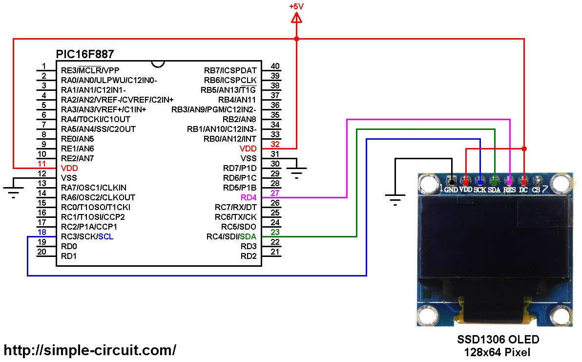
(All grounded terminals are connected together)
The PIC16F887 microcontroller has one hardware I2C module (MSSP module) with SDA on pin RC4 (#23) and SCL on pin RC3 (#18). The SDA pin of the MCU is connected to the SDA pin of the display and the SCL pin of the MCU is connected to the SCL pin of the display.
The reset pin of the display is connected to pin RD4 (#27) of the microcontroller.
The SSD1306 OLED display DC pin is connected to VDD which means the I2C slave address of the display is 0x7A.
In this project the PIC16F887 microcontroller runs with its internal oscillator @ 8 MHz, MCLR pin is configured as an input pin.
The C Code:
The following C code is for mikroC PRO for PIC compiler, it was tested with version 7.2.0.
To be able to compile the C code below with no error, a driver (& library) for the SSD1306 OLED display is required, it’s full name is SSD1306.C, download link is below:
SSD1306 OLED display driver for mikroC compiler
after the download, add the driver file (SSD1306.C) to project folder.
Full mikroC code:
Configuration words:
CONFIG1 = 0x2CD4
CONFIG2 = 0x0700
1 2 3 4 5 6 7 8 9 10 11 12 13 14 15 16 17 18 19 20 21 22 23 24 25 26 27 28 29 30 31 32 33 34 35 36 37 38 39 40 41 42 43 44 45 46 47 48 49 50 51 52 53 54 55 56 57 58 59 60 61 62 63 64 65 66 67 68 69 70 71 72 73 74 75 76 77 78 79 80 81 82 83 84 85 | /************************************************************************************** Interfacing PIC16F887 microcontroller with SSD1306 OLED display C Code for mikroC PRO for PIC compiler Internal oscillator used @ 8MHz Configuration words: CONFIG1 = 0x2CD4 CONFIG2 = 0x0700 This is a free software with NO WARRANTY. http://simple-circuit.com/ ***************************************************************************************/ // define SSD1306 reset pin (if available) #define SSD1306_RST RD4_bit #define SSD1306_RST_DIR TRISD4_bit #include <SSD1306.c> // include SSD1306 OLED driver source file char *text = "000\0"; // '\0' is the string terminator unsigned short i = 0; void main() { OSCCON = 0x70; // set internal oscillator to 8MHz delay_ms(500); // wait half a second I2C1_Init(400000); // initialize I2C communication with clock frequency of 400KHz // initialize the SSD1306 OLED with an I2C addr = 0x7A (default address) SSD1306_Init(SSD1306_SWITCHCAPVCC, SSD1306_I2C_ADDRESS); // clear the screen SSD1306_ClearDisplay(); SSD1306_GotoXY(1, 1); // move cursor to column 1, row 1 SSD1306_Print("Interfacing PIC16F887 with SSD1306 OLED display"); // print text delay_ms(5000); // wait 5 seconds // clear the screen SSD1306_ClearDisplay(); SSD1306_GotoXY(6, 2); // move cursor to column 6, row 2 SSD1306_Print("Hello world!"); delay_ms(2000); SSD1306_StartScrollRight(1, 1); delay_ms(3000); SSD1306_StopScroll(); SSD1306_StartScrollLeft(1, 1); delay_ms(3000); SSD1306_StopScroll(); SSD1306_StartScrollDiagRight(1, 1); delay_ms(3000); SSD1306_StopScroll(); SSD1306_StartScrollDiagLeft(1, 1); delay_ms(3000); SSD1306_StopScroll(); delay_ms(3000); SSD1306_ClearDisplay(); SSD1306_GotoXY(6, 2); SSD1306_Print("Hello world!"); delay_ms(2000); while(1) { text[0] = (i / 100) % 10 + '0'; // extract hundreds digit text[1] = (i / 10) % 10 + '0'; // extract tens digit text[2] = i % 10 + '0'; // extract ones digit SSD1306_GotoXY(10, 5); SSD1306_Print(text); i += 1; // increment i delay_ms(500); } } // End of code. |
The simulation of this project using Proteus should be as shown in the following video where PIC16F877A MCU is used:
Other examples where PIC16F887 microcontroller and SSD1306 OLED display are used:
PIC MCU with SSD1306 OLED and DHT11 sensor | mikroC Projects
PIC MCU with SSD1306 OLED and DHT22 sensor | mikroC Projects
PIC16F887 Interfacing with SSD1306 and DS1307 | mikroC Projects
PIC MCU with SSD1306 OLED and DS3231 RTC | mikroC Projects
Interface PIC MCU with DS18B20 sensor and SSD1306 | mikroC Projects
I have version 7.6.0 of MikroC (free version) and this will not compile. Line 72 of ssd1306.c : 72 355 Redefinition of ‘_i2caddr [SSD1306.c] ‘. ‘_i2caddr’ already defined in ‘Oled.c’ SSD1306.c
I’m lost.
Joe
oops, I included the library in the project and I guess it was evaluating it twice. I got it to compile but doesn’t work. Changed the address to 0x78 and now it’s working. 🙂
Hello,
I’ve looked at your program. I’ve written myself a driver for the oled but for the pic18F and in assembly language. I noticed that each command that you send is encapsulated in a I2C START condition, the address of the oled, the ‘control byte’ (all zeros), then a single ‘command byte’, then a STOP condition. However it is possible to send multiply ‘command bytes directly after each other if you use the control byte of all zeros (for commands) and 0x40 (for display data). This saves clock cycles. So in summary the sequence of events CAN be:
|I2C START condition| address + R/W| control byte (0x0)| …… as many command bytes (with parameters) as you like | I2C STOP condition|
The manual is awful in explaining this, so I had to figure this out by trial and error. It works. Hope this is helpful.
can this be compiled with a Microchip xc8 compiler too?
No you can’t, it’s just for mikroC PRO for PIC compiler!
I have modified it to use with xc8 compiler bitbanging it to oled display with 3 fonts! The original Simple Projects font, 10×16 and 20×32 font. Thanks you very much Simple Projects for this magnificent programm and discription.
Thank You for this amazing tutorial, Really helped me a lot
Hey This is really helpful and thank you for posting it! One question …is there an easy way to mod this to increase the font size?…I don’t even mean make it configurable but just scale it in the driver code?
You’ve to do some modifications to the driver code, increasing the font size decreases number of characters the display can show!
F887_oled.c -> “F887_oled.hex”
The f887_oled.hex file did not work after Compile.
So if you give me a hex file that you compiled, I will try to test it. If you send me a hex file by email, I will try to find out what the problem is. Thank you for your help
1. Interfacing PIC16F887 microcontroller with SSD1306 OLED display
C Code for mikroC PRO for PIC compiler I2C mode
16f887_oled.c -> “16f887_oled.h” -> Can I receive a hex file by email?
2. Interfacing PIC16F887 microcontroller with SSD1306 OLED display
C Code for mikroC PRO for PIC compiler SPI mode program is required. help me.
1. After compiling the C code with mikroC PRO for PIC compiler you’ll get the HEX file!
2. Right now I’ve no SPI mode driver for the SSD1306 OLED display.
SSD1306 Please give me a SPI program.
This example is for I2C mode, there is no SPI mode example right now!
위에프로그램 hex 파일을 제가 받아볼수있도록 꼭좀 부탁합니다 Email로 …..
0 1 mikroCPIC1618.exe -MSF -DBG -pP16F887 -DL -O11111114 -fo8 -N”C:\Users\Public\Documents\Mikroelektronika\mikroC PRO for PIC\16F887_OLED\F887_OLED.mcppi” -SP”C:\Users\Public\Documents\Mikroelektronika\mikroC PRO for PIC\Defs\” -SP”C:\Users\Public\Documents\Mikroelektronika\mikroC PRO for PIC\Uses\P16\” -SP”C:\Users\Public\Documents\Mikroelektronika\mikroC PRO for PIC\16F887_OLED\” -IP”C:\Users\Public\Documents\Mikroelektronika\mikroC PRO for PIC\Uses\P16\” -IP”C:\Users\Public\Documents\Mikroelektronika\mikroC PRO for PIC\16F887_OLED\” “F887_OLED.c” “__Lib_Math.mcl” “__Lib_MathDouble.mcl” “__Lib_System.mcl” “__Lib_Delays.mcl” “__Lib_SoftI2C.mcl” “__Lib_SoftSPI.mcl” “__Lib_I2C_c34.mcl” “__Lib_SPI_c345.mcl” “__Lib_SPIGlcd.mcl” “__Lib_SPILcd.mcl” “__Lib_SPILcd8.mcl”
hint: 0 1139 Available RAM: 352 [bytes], Available ROM: 8192 [bytes]
diagnostics: 0 122 Compilation Started stdint.h
diagnostics: 84 123 Compiled Successfully F887_OLED.c
hint: 363 1164 Variable ‘font_c’ has been eliminated by optimizer F887_OLED.c
hint: 403 1164 Variable ‘line’ has been eliminated by optimizer F887_OLED.c
diagnostics: 0 127 All files Compiled in 453 ms
hint: 0 1144 Used RAM (bytes): 130 (37%) Free RAM (bytes): 222 (63%) Used RAM (bytes): 130 (37%) Free RAM (bytes): 222 (63%)
hint: 0 1144 Used ROM (program words): 1772 (22%) Free ROM (program words): 6420 (78%) Used ROM (program words): 1772 (22%) Free ROM (program words): 6420 (78%)
diagnostics: 0 125 Project Linked Successfully F887_OLED.mcppi
diagnostics: 0 128 Linked in 360 ms
diagnostics: 0 129 Project ‘F887_OLED.mcppi’ completed: 1000 ms
diagnostics: 0 103 Finished successfully: 12 11 2018, 21:43:17 F887_OLED.mcppi
196 324 Undeclared identifier ‘I2C1_Start’ in expression ssd1306.c
i have a compilation error like the one above
Make sure the I2C library is checked (mikroC IDE —> Library Manager and search for I2C, then check it).