This post shows how to build a simple real time clock using PIC16F887 microcontroller and DS1307 (or DS3231) RTC chip. Time and date are displayed on 16×2 LCD screen and they can be set with two push buttons connected to the MCU.
The compiler used in this project is Microchip MPLAB XC8 (MPLAB X IDE with MPLAB XC8 compiler).
Related Projects:
Interfacing LCD with PIC microcontroller | MPLAB Projects
Hardware Required:
The components required for this project are listed below.
- PIC16F887 microcontroller — datasheet
- DS3231 (or DS1307) board — DS1307 datasheet — DS3231 datasheet
- 16×2 LCD screen
- 2 x pushbutton
- 330 ohm resistor
- 10k ohm variable resistor or potentiometer
- 3V coin cell battery
- 5V source
- Breadboard
- Jumper wires
Generally the DS1307 or DS3231 board contains the main chip (DS1307 or DS3231 IC), 2 pull-ups resistors and battery holder.
Interfacing DS1307/DS3231 RTC with PIC microcontroller circuit:
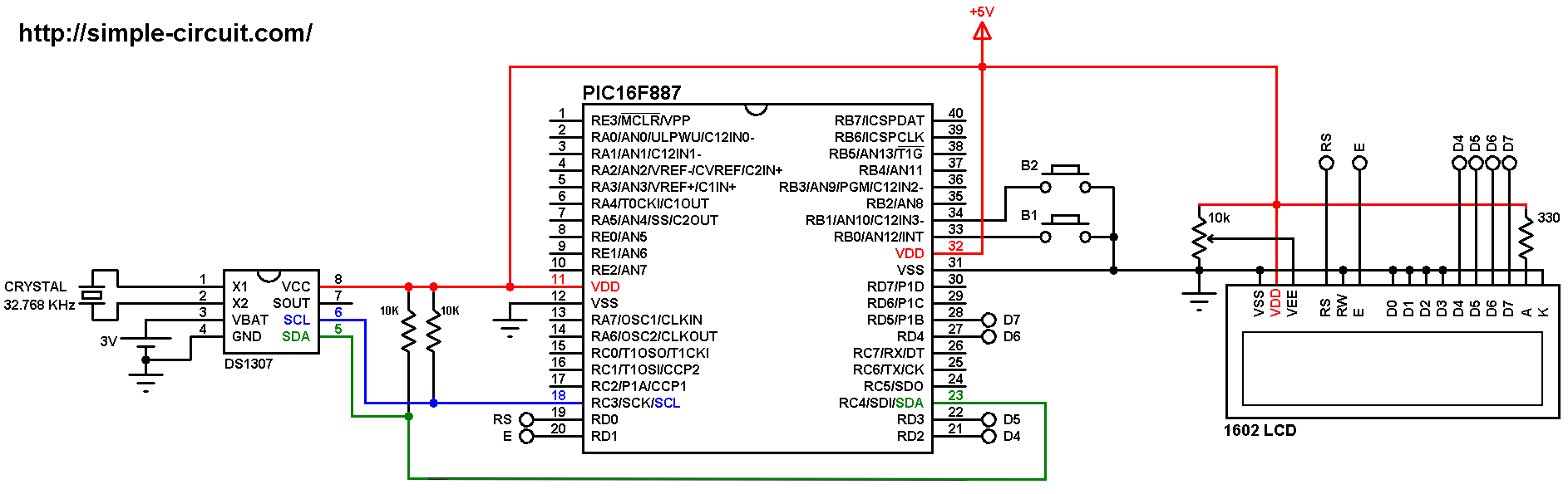
The following image shows circuit connection of PIC16F887 MCU, DS1307 RTC and 16×2 LCD screen.
and the below image shows the same circuit but with DS3231 board instead of DS1307:

(All grounded terminals are connected together)
The two push buttons in the circuit are used to set time and date of the real time clock, button 1 (B1) is connected to RB0 pin (#33) and button 2 (B2) is connected to RB1 pin (#34) of the PIC16F887 MCU.
The 16×2 LCD screen is connected to the PIC16F887 microcontroller as follows:
RS —> RD0 pin
E —> RD1 pin
D4 —> RD2 pin
D5 —> RD3 pin
D6 —> RD4 pin
D7 —> RD5 pin
VSS, RW, D0, D1, D2, D3 and K are connected to circuit GND (ground)
VEE to the variable resistor (or potentiometer) output pin
VDD to +5V and A to +5V through 330 ohm resistor
VEE pin is used to control the contrast of the LCD. A (anode) and K (cathode) are the back light LED pins.
In this project the PIC16F887 microcontroller runs with its internal oscillator @ 8 MHz, MCLR pin is configured as an input pin.
Interfacing DS1307/DS3231 RTC with PIC microcontroller C code:
The C code below is for MPLAB XC8 compiler, it was tested with version 2.00 installed on MPLAB X IDE version 5.05.
To be able to compile the C code, a small LCD library for MPLAB XC8 compiler is required which can be downloaded from the following link:
MPLAB XC8 LCD Library
after the download, add the library file (LCD_Lib.c) to project folder.
I2C Functions:
The MPLAB XC8 compiler doesn’t have any I2C library for the PIC16F887 microcontroller which means we’ve to write own I2C function codes.
The PIC16F887 has one MSSP module which can work in I2C mode. For that I wrote some functions which allowed me to communicate with the RTC chip using the MSSP module:
void I2C_Init(uint32_t i2c_clk_freq) : initializes the MSSP module in I2C mode (master mode) with a clock frequency of i2c_clk_freq.
void I2C_Start() : this function sends a start signal to the I2C slave device.
void I2C_Repeated_Start() : sends a repeated start signal.
void I2C_Stop() : sends a stop signal.
void I2C_Write(uint8_t i2c_data) : writes data (i2c_data) to the I2C device.
uint8_t I2C_Read(uint8_t ack) : reads (& returns) data from I2C device, this function sends acknowledge pulse if ack = 1.
RTC Functions:
The RTC chip (DS1307 or DS3231) works with BCD format only, to convert the BCD to decimal and vise versa I used the 2 functions below. Before displaying (after reading from RTC IC), the data have to be converted from BCD to decimal, and before writing to the RTC IC (after editing the parameters) the data have to be converted from decimal to BCD:
uint8_t bcd_to_decimal(uint8_t number)
uint8_t decimal_to_bcd(uint8_t number)
Each function returns the converted value of the variable number.
void RTC_display() : displays time and date, before printing them on the LCD, time and date data are converted from BCD format to decimal format using the function bcd_to_decimal(uint8_t number) .
uint8_t edit(uint8_t x, uint8_t y, uint8_t parameter) : I used this function to edit time and date parameters (minutes, hours, date, month and year). I used a variable named i to distinguish between the parameters:
i = 0, 1 : hours and minutes respectively
i = 2, 3, 4: date, month and year respectively
After the edit of time and date, the data have to be converted back to BCD format using the function decimal_to_bcd(uint8_t number) and written to the RTC chip.
void blink() : this small function works as a delay except that it can be interrupted by buttons B1 (connected to RB0) and B2 (connected to RB1). When called and without pressing any button the total time is 100 x 5ms = 500ms. With this function we can see the blinking of the selected parameter with a frequency of 1 Hz. So a delay of 500ms comes after the print of the selected parameter and after that delay, 2 spaces are printed which make the parameter disappears from the screen and another 500ms delay comes after the print of the 2 spaces.
The microcontroller used in this example is PIC16F887, configuration words are:
1 2 | #pragma config CONFIG1 = 0x2CD4 #pragma config CONFIG2 = 0x0700 |
Where:
- In-Circuit Debugger disabled
- Low voltage programming disabled
- Fail-Safe Clock Monitor enabled
- Internal/External Switchover mode enabled
- Brown-out Reset (BOR) disabled
- Data memory code protection disabled
- Program memory code protection disabled
- RE3/MCLR pin function is digital input, MCLR internally tied to VDD
- Power-up Timer (PWRT) disabled
- Watchdog Timer (WDT) disabled
- INTOSCIO oscillator: I/O function on RA6/OSC2/CLKOUT pin, I/O function on RA7/OSC1/CLKIN
- Flash Program Memory Self Write disabled
- Brown-out Reset set to 4.0V
Full MPLAB XC8 code:
1 2 3 4 5 6 7 8 9 10 11 12 13 14 15 16 17 18 19 20 21 22 23 24 25 26 27 28 29 30 31 32 33 34 35 36 37 38 39 40 41 42 43 44 45 46 47 48 49 50 51 52 53 54 55 56 57 58 59 60 61 62 63 64 65 66 67 68 69 70 71 72 73 74 75 76 77 78 79 80 81 82 83 84 85 86 87 88 89 90 91 92 93 94 95 96 97 98 99 100 101 102 103 104 105 106 107 108 109 110 111 112 113 114 115 116 117 118 119 120 121 122 123 124 125 126 127 128 129 130 131 132 133 134 135 136 137 138 139 140 141 142 143 144 145 146 147 148 149 150 151 152 153 154 155 156 157 158 159 160 161 162 163 164 165 166 167 168 169 170 171 172 173 174 175 176 177 178 179 180 181 182 183 184 185 186 187 188 189 190 191 192 193 194 195 196 197 198 199 200 201 202 203 204 205 206 207 208 209 210 211 212 213 214 215 216 217 218 219 220 221 222 223 224 225 226 227 228 229 230 231 232 233 234 235 236 237 238 239 240 241 242 243 244 245 246 247 248 249 250 251 252 253 254 255 256 257 258 259 260 261 262 263 264 265 266 267 268 269 270 271 272 273 274 275 276 277 278 279 280 281 282 283 284 285 286 287 | /* * Real time clock using PIC16F887 MCU and RTC chip (DS1307, DS3231 or DS3232) * Time and date are displayed on 1602 LCD screen. * C Code for MPLAB XC8 compiler. * Internal oscillator used @ 8MHz. * This is a free software with NO WARRANTY. * http://simple-circuit.com/ */ // set configuration words #pragma config CONFIG1 = 0x2CD4 #pragma config CONFIG2 = 0x0700 // button definitions #define button1 RB0 // button B1 is connected to RB0 pin #define button2 RB1 // button B2 is connected to RB1 pin //LCD module connections #define LCD_RS RD0 #define LCD_EN RD1 #define LCD_D4 RD2 #define LCD_D5 RD3 #define LCD_D6 RD4 #define LCD_D7 RD5 #define LCD_RS_DIR TRISD0 #define LCD_EN_DIR TRISD1 #define LCD_D4_DIR TRISD2 #define LCD_D5_DIR TRISD3 #define LCD_D6_DIR TRISD4 #define LCD_D7_DIR TRISD5 //End LCD module connections #include <xc.h> #define _XTAL_FREQ 8000000 #include <stdint.h> // include stdint header #include "LCD_Lib.c" // include LCD driver source file // variables declaration uint8_t i, second, minute, hour, m_day, month, year; /********************** I2C functions **************************/ void I2C_Init(uint32_t i2c_clk_freq) { SSPCON = 0x28; // configure MSSP module to work in I2C mode SSPADD = (_XTAL_FREQ/(4 * i2c_clk_freq)) - 1; // set I2C clock frequency SSPSTAT = 0; } void I2C_Start() { while ((SSPSTAT & 0x04) || (SSPCON2 & 0x1F)); // wait for MSSP module to be free (not busy) SEN = 1; // initiate start condition } void I2C_Repeated_Start() { while ((SSPSTAT & 0x04) || (SSPCON2 & 0x1F)); // wait for MSSP module to be free (not busy) RSEN = 1; // initiate repeated start condition } void I2C_Stop() { while ((SSPSTAT & 0x04) || (SSPCON2 & 0x1F)); // wait for MSSP module to be free (not busy) PEN = 1; // initiate stop condition } void I2C_Write(uint8_t i2c_data) { while ((SSPSTAT & 0x04) || (SSPCON2 & 0x1F)); // wait for MSSP module to be free (not busy) SSPBUF = i2c_data; // update buffer } uint8_t I2C_Read(uint8_t ack) { uint8_t _data; while ((SSPSTAT & 0x04) || (SSPCON2 & 0x1F)); // wait for MSSP module to be free (not busy) RCEN = 1; while ((SSPSTAT & 0x04) || (SSPCON2 & 0x1F)); // wait for MSSP module to be free (not busy) _data = SSPBUF; // read data from buffer while ((SSPSTAT & 0x04) || (SSPCON2 & 0x1F)); // wait for MSSP module to be free (not busy) // send acknowledge pulse ? (depends on ack, if 1 send, otherwise don't send) ACKDT = !ack; ACKEN = 1; return _data; // return data read } /********************** end I2C functions **********************/ // a small function for button1 (B1) debounce __bit debounce () { uint8_t count = 0; for(uint8_t i = 0; i < 5; i++) { if (button1 == 0) count++; __delay_ms(10); } if(count > 2) return 1; else return 0; } /********************** RTC chip functions *********************/ // convert BCD to decimal function uint8_t bcd_to_decimal(uint8_t number) { return((number >> 4) * 10 + (number & 0x0F)); } // convert decimal to BCD function uint8_t decimal_to_bcd(uint8_t number) { return(((number / 10) << 4) + (number % 10)); } // display time and date function void RTC_display() { static char Time[] = "TIME: 00:00:00"; static char Date[] = "DATE: 00/00/2000"; // convert data from BCD format to decimal format second = bcd_to_decimal(second); minute = bcd_to_decimal(minute); hour = bcd_to_decimal(hour); m_day = bcd_to_decimal(m_day); month = bcd_to_decimal(month); year = bcd_to_decimal(year); // end conversion // update time Time[6] = hour / 10 + '0'; Time[7] = hour % 10 + '0'; Time[9] = minute / 10 + '0'; Time[10] = minute % 10 + '0'; Time[12] = second / 10 + '0'; Time[13] = second % 10 + '0'; // update date Date[6] = m_day / 10 + '0'; Date[7] = m_day % 10 + '0'; Date[9] = month / 10 + '0'; Date[10] = month % 10 + '0'; Date[14] = year / 10 + '0'; Date[15] = year % 10 + '0'; LCD_Goto(1, 1); // go to column 1, row 1 LCD_Print(Time); // print time LCD_Goto(1, 2); // go to column 1, row 2 LCD_Print(Date); // print date } // make editing parameter blinks function void blink() { uint8_t j = 0; while(j < 100 && button1 && button2) { j++; __delay_ms(5); } } // Edit time and date function uint8_t edit(uint8_t x, uint8_t y, uint8_t parameter) { while(debounce()); // call debounce function (wait for B1 to be released) while(1) { while(!button2) // if button B2 is pressed { parameter++; if(i == 0 && parameter > 23) // if hours > 23 ==> hours = 0 parameter = 0; if(i == 1 && parameter > 59) // if minutes > 59 ==> minutes = 0 parameter = 0; if(i == 2 && parameter > 31) // if date > 31 ==> date = 1 parameter = 1; if(i == 3 && parameter > 12) // if month > 12 ==> month = 1 parameter = 1; if(i == 4 && parameter > 99) // if year > 99 ==> year = 0 parameter = 0; LCD_Goto(x, y); LCD_PutC(parameter / 10 + '0'); LCD_PutC(parameter % 10 + '0'); __delay_ms(200); } LCD_Goto(x, y); LCD_Print(" "); // print 2 spaces blink(); LCD_Goto(x, y); LCD_PutC(parameter / 10 + '0'); LCD_PutC(parameter % 10 + '0'); blink(); if(!button1) // if button B1 is pressed if(debounce()) // call debounce function (make sure if B1 is pressed) { i++; // increment 'i' for the next parameter return parameter; // return parameter value and exit } } } /********************** end RTC chip functions *****************/ /*************************** main function *********************/ void main(void) { OSCCON = 0X70; // set internal oscillator to 8MHz ANSELH = 0; // configure all PORTB pins as digital // enable RB0 and RB1 internal pull ups nRBPU = 0; // clear RBPU bit (OPTION_REG.7) WPUB = 0x03; // WPUB register = 0b00000011 __delay_ms(1000); I2C_Init(100000); // initialize I2C bus with clock frequency of 100kHz LCD_Begin(); // initialize LCD module while(1) { if(!button1) // if button B1 is pressed if(debounce()) // call debounce function (make sure if B1 is pressed) { i = 0; hour = edit(7, 1, hour); minute = edit(10, 1, minute); m_day = edit(7, 2, m_day); month = edit(10, 2, month); year = edit(15, 2, year); while(debounce()); // call debounce function (wait for button B1 to be released) // convert decimal to BCD minute = decimal_to_bcd(minute); hour = decimal_to_bcd(hour); m_day = decimal_to_bcd(m_day); month = decimal_to_bcd(month); year = decimal_to_bcd(year); // end conversion // Write data to DS3231 RTC I2C_Start(); // start I2C I2C_Write(0xD0); // RTC chip address I2C_Write(0); // send register address I2C_Write(0); // reset seconds and start oscillator I2C_Write(minute); // write minute value to RTC chip I2C_Write(hour); // write hour value to RTC chip I2C_Write(1); // write day value (not used) I2C_Write(m_day); // write date value to RTC chip I2C_Write(month); // write month value to RTC chip I2C_Write(year); // write year value to RTC chip I2C_Stop(); // stop I2C __delay_ms(200); } // read current time and date from the RTC chip I2C_Start(); // start I2C I2C_Write(0xD0); // RTC chip address I2C_Write(0); // send register address I2C_Repeated_Start(); // restart I2C I2C_Write(0xD1); // initialize data read second = I2C_Read(1); // read seconds from register 0 minute = I2C_Read(1); // read minutes from register 1 hour = I2C_Read(1); // read hour from register 2 I2C_Read(1); // read day from register 3 (not used) m_day = I2C_Read(1); // read date from register 4 month = I2C_Read(1); // read month from register 5 year = I2C_Read(0); // read year from register 6 I2C_Stop(); // stop I2C RTC_display(); // print time & date __delay_ms(50); // wait 50 ms } } /*************************** end main function ********************************/ |
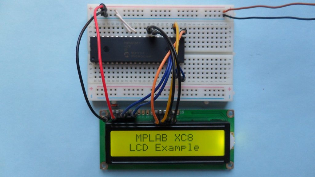
Hardware circuit of this project should give a result as shown in the following video where DS3231 board is used:

Have you worked out 12 hour mode using AM and PM ? It works great in 24 hour mode?
your code too complicated
Did u use mikroc?
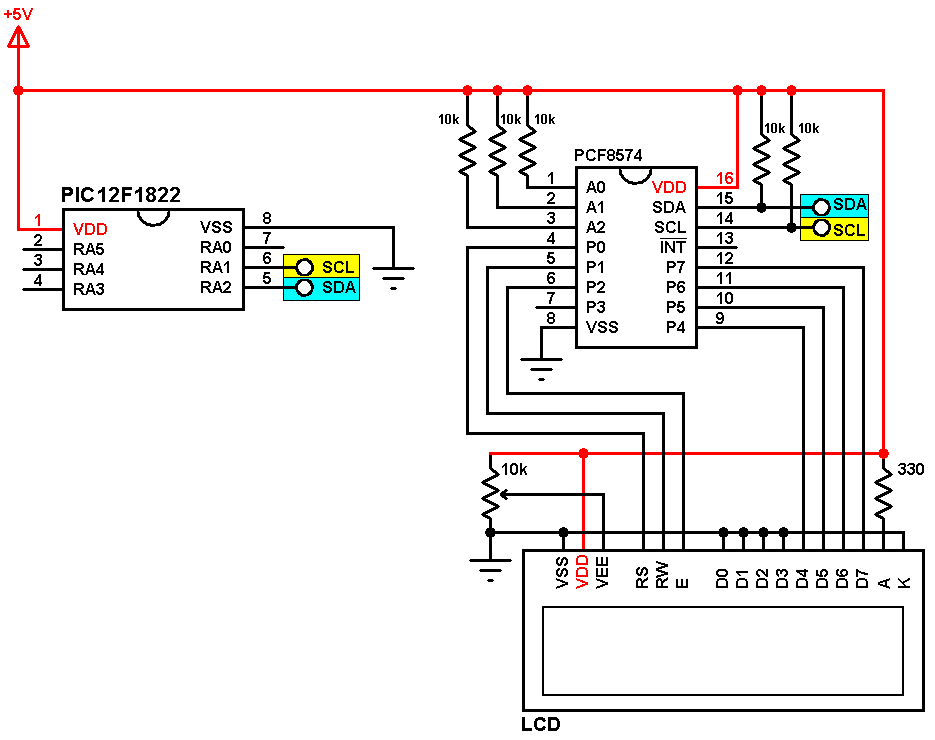
Why didn’t you use an I2C LCDs in that project like you did in the other project version in MIkroC? Is there any problem with I2C LCDs? Is there any problem with the library that you share on your site?
I’m doing a project with that measures pressure and show the value on a LCD with a PIC16F877A and I’ve been searching for some library or example code for MPLab that show continuous data like you did in this project, but I couldn’t find some that works well.
Not working hours, minutes, seconds, date, month, year are shown as “@5” please help
That means there’s a bad connection between the MCU and the RTC (DS1307 or DS3231)!
I can’t understand the blink of numbers pls explain it
Dear Sir, can you please guide how can we improvise time based multiple relay operation in this code. Means we can be able to set multiple on & off time for relay. Thanks a lot for this tutorial.