This topic shows how to decode IR (Infra-Red) remote controls which use NEC protocol (NEC and extended NEC) using PIC16F887 microcontroller. Results are displayed on 16×2 LCD screen.
The compiler used in this project is Microchip MPLAB XC8 (MPLAB X IDE with MPLAB XC8 compiler).
About NEC protocol:
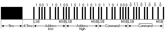
The complete extended NEC protocol message is started by 9ms burst followed by 4.5ms space which is then followed by Address and Command. The address is 16-bit length and the command is transmitted twice (8 bits + 8 bits) where in the second time all bits are inverted and can be used for verification of the received message. The following drawing shows an extended NEC message example.
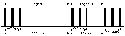
The NEC protocol uses pulse distance encoding of the bits. Each pulse is a 562.5µs long with carrier frequency of 38KHz. Logic bits are transmitted as follows:
Logic 0: 562.5µs pulse burst followed by a 562.5µs space, with a total transmit time of 1125µs (562.5 x 2).
Logic 1: a 562.5µs pulse burst followed by a 1687.5µs (562.5 x 3) space, with a total transmit time of 2250µs (562.5 x 4).
The difference between the NEC protocol and the extended NEC protocol is that in the first one the address (16-bit long) is transmitted twice (8-bit + 8-bit) where in the second time all bits are inverted (the same thing with command and inverted command).
In the extended NEC protocol the second 8 bits are independent of the first ones.
Related Project:
To see how to interface PIC microcontroller with LCD module using MPLAB XC8 compiler, read the following post:
Interfacing LCD with PIC microcontroller | MPLAB Projects
Hardware Required:
- PIC16F887 microcontroller —-> datasheet
- IR Receiver
- 16×2 LCD screen
- 10k ohm variable resistor or potentiometer
- 330 ohm resistor
- 5V Power source
- Protoboard
- Jumper wires
NEC Remote control decoder with PIC microcontroller circuit:
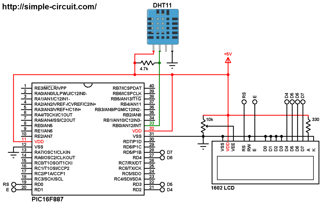
The following image shows project circuit diagram.
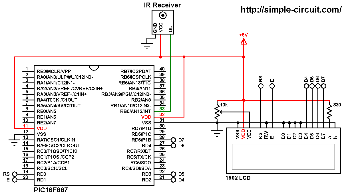
(All grounded terminals are connected together)
Generally the IR receiver has 3 pins: GND, VCC and data. The data pin is connected to pin RB0 of the PIC16F887 microcontroller.
The 16×2 LCD screen is connected to the PIC16F887 microcontroller as follows:
RS —> RD0 pin
E —> RD1 pin
D4 —> RD2 pin
D5 —> RD3 pin
D6 —> RD4 pin
D7 —> RD5 pin
VSS, RW, D0, D1, D2, D3 and K are connected to circuit GND (ground)
VEE to the variable resistor (or potentiometer) output pin
VDD to +5V and A to +5V through 330 ohm resistor
VEE pin is used to control the contrast of the LCD. A (anode) and K (cathode) are the back light LED pins.
In this project the PIC16F887 microcontroller runs with its internal oscillator @ 8 MHz, MCLR pin is configured as an input pin.
NEC Remote control decoder with PIC microcontroller C code:
The C code below is for MPLAB XC8 compiler, it was tested with version 2.00 installed on MPLAB X IDE version 5.05.
To be able to compile the C code, a small LCD library for MPLAB XC8 compiler is required which can be downloaded from the following link:
MPLAB XC8 LCD Library
after the download, add the library file (LCD_Lib.c) to project folder.
Programming hints:
The message of the NEC protocol is 32-bit long, address (16 bits), command (8 bits), and inverted command (8 bits). Before the 32 bits there is 9ms burst and 4.5ms space.
A logic 1 is represented by 562.5µs burst and 562.5µs space (total of 1125µs) and a logic 0 is represented by 562.5µs burst and 1687.5µs space (total of 2250µs).
Keep in mind that the IR receiver output is always inverted.
The interval [ 9500µs, 8500µs ] is used for the 9ms pulse and for the 4.5ms space the interval [ 5000µs, 4000µs ] is used.
The 562.5µs pulse is checked with the interval [ 700µs, 400µs ] .
For the 562.5µs or 1687.5µs space I used the interval [ 1800µs, 400µs ], and to know if its a short or long space I used a length of 1000µs.
The output of the IR receiver is connected to external interrupt pin (RB0) (interrupt on change) and every change in the pin status generates an interrupt and Timer1 starts ticking, Timer1 value will be used in the next interrupt, this means Timer1 measures the time between two interrupts which is pulse time or space time. Also, Timer1 interrupt is used to reset the decoding process in case of very long pulse or space.
Timer1 time step is 1µs (Timer1 increments every 1µs). If you use mcu frequency other than 8MHz, make sure to keep Timer1 time step to 1µs, otherwise time intervals have to be changed.
The decoding results are displayed on 1602 LCD screen connected to PORTD.
The microcontroller used in this example is PIC16F887, configuration words are:
1 2 | #pragma config CONFIG1 = 0x2CD4 #pragma config CONFIG2 = 0x0700 |
Where:
- In-Circuit Debugger disabled
- Low voltage programming disabled
- Fail-Safe Clock Monitor enabled
- Internal/External Switchover mode enabled
- Brown-out Reset (BOR) disabled
- Data memory code protection disabled
- Program memory code protection disabled
- RE3/MCLR pin function is digital input, MCLR internally tied to VDD
- Power-up Timer (PWRT) disabled
- Watchdog Timer (WDT) disabled
- INTOSCIO oscillator: I/O function on RA6/OSC2/CLKOUT pin, I/O function on RA7/OSC1/CLKIN
- Flash Program Memory Self Write disabled
- Brown-out Reset set to 4.0V
Full MPLAB XC8 code:
1 2 3 4 5 6 7 8 9 10 11 12 13 14 15 16 17 18 19 20 21 22 23 24 25 26 27 28 29 30 31 32 33 34 35 36 37 38 39 40 41 42 43 44 45 46 47 48 49 50 51 52 53 54 55 56 57 58 59 60 61 62 63 64 65 66 67 68 69 70 71 72 73 74 75 76 77 78 79 80 81 82 83 84 85 86 87 88 89 90 91 92 93 94 95 96 97 98 99 100 101 102 103 104 105 106 107 108 109 110 111 112 113 114 115 116 117 118 119 120 121 122 123 124 125 126 127 128 129 130 131 132 133 134 135 136 137 138 139 140 141 142 143 144 145 146 147 148 149 150 151 152 153 154 155 156 157 158 159 160 161 162 163 164 165 166 167 168 169 170 171 172 173 174 175 176 177 178 179 180 181 182 183 184 185 186 187 188 189 190 191 192 193 | /* * NEC Protocol IR remote control decoder with PIC16F887 MCU. * C Code for MPLAB XC8 compiler. * Internal oscillator used @ 8MHz. * This is a free software with NO WARRANTY. * http://simple-circuit.com/ */ // set configuration words #pragma config CONFIG1 = 0x2CD4 #pragma config CONFIG2 = 0x0700 //LCD module connections #define LCD_RS RD0 #define LCD_EN RD1 #define LCD_D4 RD2 #define LCD_D5 RD3 #define LCD_D6 RD4 #define LCD_D7 RD5 #define LCD_RS_DIR TRISD0 #define LCD_EN_DIR TRISD1 #define LCD_D4_DIR TRISD2 #define LCD_D5_DIR TRISD3 #define LCD_D6_DIR TRISD4 #define LCD_D7_DIR TRISD5 //End LCD module connections #include <xc.h> #define _XTAL_FREQ 8000000 #include <stdio.h> // for sprintf #include <stdint.h> // include stdint header #include "LCD_Lib.c" // include LCD driver source file __bit nec_ok; char text[5]; uint8_t nec_state, bit_n; uint16_t timer_value; uint32_t nec_code; // interrupt ISRs void __interrupt() EXT(void) { /*************** start external interrupt ISR ***************/ if (RBIF && (RB0 || !RB0)) // PORTB change ISR (& clear mismatch condition) { RBIF = 0; // clear PORTB interrupt flag bit if(nec_state != 0) { timer_value = (TMR1H << 8) | TMR1L; // store Timer1 value TMR1H = TMR1L = 0; // reset Timer1 } switch(nec_state) { case 0 : // start receiving IR data (we're at the beginning of 9ms pulse) TMR1H = TMR1L = 0; // reset Timer1 TMR1ON = 1; // enable Timer1 nec_state = 1; // next state: end of 9ms pulse (start of 4.5ms space) bit_n = 0; break; case 1 : // End of 9ms pulse if((timer_value > 9500) || (timer_value < 8500)) { // invalid interval ==> stop decoding and reset nec_state = 0; // reset decoding process TMR1ON = 0; // disable Timer1 } else nec_state = 2; // next state: end of 4.5ms space (start of 562µs pulse) break; case 2 : // End of 4.5ms space if((timer_value > 5000) || (timer_value < 4000)) { // invalid interval ==> stop decoding and reset nec_state = 0; // reset decoding process TMR1ON = 0; // disable Timer1 } else nec_state = 3; // next state: end of 562µs pulse (start of 562µs or 1687µs space) break; case 3 : // End of 562µs pulse if((timer_value > 700) || (timer_value < 400)) { // invalid interval ==> stop decoding and reset TMR1ON = 0; // disable Timer1 nec_state = 0; // reset decoding process } else nec_state = 4; // next state: end of 562µs or 1687µs space break; case 4 : if((timer_value > 1800) || (timer_value < 400)) { // invalid interval ==> stop decoding and reset TMR1ON = 0; // disable Timer1 nec_state = 0; // reset decoding process } else { if( timer_value > 1000) // if space width > 1ms (short space) nec_code |= (uint32_t)1 << (31 - bit_n); // write 1 to bit (31 - bit_n) else // if space width < 1ms (long space) nec_code &= ~((uint32_t)1 << (31 - bit_n)); // write 0 to bit (31 - bit_n) bit_n++; if(bit_n > 31) { nec_ok = 1; // decoding process OK RBIE = 0; // disable PORTB change interrupt } else nec_state = 3; // next state: end of 562µs pulse (start of 562µs or 1687µs space) break; } // end " else " } // end " switch(nec_state) " } // end " if (RBIF && (RB0 || !RB0)) " /*************** end external interrupt ISR ***************/ /*************** start Timer1 ISR ***************/ if (TMR1IF) // Timer1 ISR { TMR1IF = 0; // clear Timer1 overflow flag bit nec_state = 0; // reset decoding process TMR1ON = 0; // disable Timer1 } /*************** end Timer1 ISR ***************/ } /*************************** main function *********************/ void main(void) { OSCCON = 0x70; // set internal oscillator to 8MHz ANSELH = 0; // configure all PORTB pins as digital TMR1IF = 0; // clear Timer1 overflow interrupt flag bit RBIF = 0; // clear PORTB change interrupt flag bit TMR1IE = 1; // enable Timer1 overflow interrupt T1CON = 0x10; // set Timer1 clock source to internal with 1:2 prescaler (Timer1 clock = 1MHz) INTCON = 0xC8; // enable global, peripheral and PORTB change interrupts IOCB0 = 1; // enable RB0 pin change interrupt nec_ok = 0; nec_state = 0; __delay_ms(1000); // wait 1 second LCD_Begin(); // initialize LCD module LCD_Goto(1, 1); // move cursor to column 1, row 1 LCD_Print("Address:0x0000"); LCD_Goto(1, 2); // move cursor to column 1, row 2 LCD_Print("Com:0x00 In:0x00"); while(1) { while (!nec_ok); // wait until NEC code receiver nec_ok = 0; // reset decoding process nec_state = 0; TMR1ON = 0; // disable Timer1 uint16_t address = nec_code >> 16; uint8_t command = nec_code >> 8; uint8_t inv_command = nec_code; sprintf(text,"%04X",address); LCD_Goto(11, 1); // move cursor to column 11 line 1 LCD_Print(text); // print address sprintf(text,"%02X",command); LCD_Goto(7, 2); // move cursor to column 7 line 2 LCD_Print(text); // print command sprintf(text,"%02X",inv_command); LCD_Goto(15, 2); // move cursor to column 15 line 2 LCD_Print(text); // print inverted command RBIE = 1; // enable PORTB change interrupt } } /*************************** end main function ********************************/ |
The following video shows how this project should work:
Reference:
http://www.sbprojects.com/

Thanks!
Hello Sir,
Thanks for sharing NEC Protocol IR remote control decoder with PIC16F887 MCU C Code for MPLAB XC8 compiler.
project is working fine,i need a help, suppose i am using 10 led bar and i want to on/off all led sequentially with single long/continuous press by any remote key. now it works only one time because when i long press a key it generates repeat code followed by a command, could you please help me to rectify this problem.
Thanks,