This post shows how to use PIC16F887 microcontroller USART module in order to receive and send data from and to PC serial monitor software (hyper terminal, Arduino IDE serial monitor tool, mikroElektronika USART Terminal …) or any device that uses UART communication.
USART: Universal Synchronous/Asynchronous Receiver/Transmitter.
UART: Universal Asynchronous Receiver/Transmitter
The compiler used in this project is Microchip MPLAB XC8 (MPLAB X IDE with MPLAB XC8 compiler).
The PIC16F887 microcontroller has one USART module, this module can be used as USART or UART depending on the configuration of some registers related with the module.
In this example I’m going to use the module in UART mode.
Hardware Required:
- PIC16F887 microcontroller —-> datasheet
- USB-to-serial converter (such as FT232RL)
- 5V Power source
- Protoboard
- Jumper wires
UART Example with PIC microcontroller circuit:
the connection between PIC16F887 microcontroller and laptop (or PC) is shown below. The FT232RL module is directly connected to laptop USB port with mini USB cable.
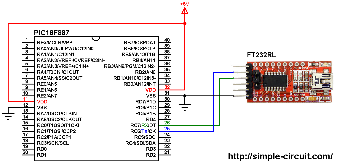
(All grounded terminals are connected together)
To be able to send/receive data from/to the microcontroller to/from the laptop we need a USB-to-Serial converter module. In this example I used the FT232RL module (the main component is FT232RL chip from FTDI), other modules can be used including the Arduino boards.
The GND pin of the USB-to-Serial converter is connected to circuit ground, pins RX and TX are respectively connected to TX (#25) and RX (#26) pins of the PIC16F887 microcontroller.
In this project the PIC16F887 microcontroller runs with its internal oscillator @ 8 MHz, MCLR pin is configured as an input pin.
UART Example with PIC microcontroller C code:
The C code below is for MPLAB XC8 compiler, it was tested with version 2.00 installed on MPLAB X IDE version 5.05.
Functions used in the C code:
First, UART registers used are:
TXSTA: RANSMIT STATUS AND CONTROL REGISTER
RCSTA: RECEIVE STATUS AND CONTROL REGISTER
SPBRG: SERIAL PORT BAUD RATE GENERATOR
RCREG: EUSART RECEIVE DATA REGISTER
TXREG: EUSART TRANSMIT DATA REGISTER —-> EUSART: Enhanced USART
void UART_Init(const uint32_t baud_rate): initializes hardware UART module with a baud rate of baud_rate.
__bit UART_Data_Ready(): this function returns 1 if there is data (in the receiver buffer) ready for reading, returns 0 if there is no data.
uint8_t UART_GetC(): returns the data which is available in the receiver buffer.
void UART_PutC(const char data): this function transmits a character (byte) data via the UART module.
void UART_Print(const char *data): transmits a text *data via the UART module. This function is based on the previous function UART_PutC.
The microcontroller used in this example is PIC16F887, configuration words are:
1 2 | #pragma config CONFIG1 = 0x2CD4 #pragma config CONFIG2 = 0x0700 |
Where:
- In-Circuit Debugger disabled
- Low voltage programming disabled
- Fail-Safe Clock Monitor enabled
- Internal/External Switchover mode enabled
- Brown-out Reset (BOR) disabled
- Data memory code protection disabled
- Program memory code protection disabled
- RE3/MCLR pin function is digital input, MCLR internally tied to VDD
- Power-up Timer (PWRT) disabled
- Watchdog Timer (WDT) disabled
- INTOSCIO oscillator: I/O function on RA6/OSC2/CLKOUT pin, I/O function on RA7/OSC1/CLKIN
- Flash Program Memory Self Write disabled
- Brown-out Reset set to 4.0V
Full MPLAB XC8 code:
1 2 3 4 5 6 7 8 9 10 11 12 13 14 15 16 17 18 19 20 21 22 23 24 25 26 27 28 29 30 31 32 33 34 35 36 37 38 39 40 41 42 43 44 45 46 47 48 49 50 51 52 53 54 55 56 57 58 59 60 61 62 63 64 65 66 67 68 69 70 71 72 73 74 75 76 77 78 79 80 81 82 83 84 85 86 87 88 89 90 91 92 93 94 95 96 97 98 99 100 101 102 103 104 105 106 107 108 109 110 111 112 113 114 115 116 117 | /* * UART Example with PIC16F887 microcontroller. * C Code for MPLAB XC8 compiler. * Internal oscillator used @ 8MHz. * This is a free software with NO WARRANTY. * http://simple-circuit.com/ */ // set configuration words #pragma config CONFIG1 = 0x2CD4 #pragma config CONFIG2 = 0x0700 #include <xc.h> #define _XTAL_FREQ 8000000 #include <stdio.h> // for sprintf #include <stdint.h> // include stdint header /********************** UART functions **************************/ void UART_Init(const uint32_t baud_rate) { int16_t n = ( _XTAL_FREQ / (16 * baud_rate) ) - 1; if (n < 0) n = 0; if (n > 255) // low speed { n = ( _XTAL_FREQ / (64 * baud_rate) ) - 1; if (n > 255) n = 255; SPBRG = n; TXSTA = 0x20; // transmit enabled, low speed mode } else // high speed { SPBRG = n; TXSTA = 0x24; // transmit enabled, high speed mode } RCSTA = 0x90; // serial port enabled, continues receive enabled } __bit UART_Data_Ready() { return RCIF; // return RCIF bit (register PIR1, bit 5) } uint8_t UART_GetC() { while (RCIF == 0) ; // wait for data receive if (OERR) // if there is overrun error { // clear overrun error bit CREN = 0; CREN = 1; } return RCREG; // read from EUSART receive data register } void UART_PutC(const char data) { while (TRMT == 0); // wait for transmit shift register to be empty TXREG = data; // update EUSART transmit data register } void UART_Print(const char *data) { uint8_t i = 0; while (data[i] != '\0') UART_PutC (data[i++]); } /********************** end UART functions **************************/ const char message[] = "PIC16F887 microcontroller UART example" ; // main function void main(void) { OSCCON = 0x70; // set internal oscillator to 8MHz UART_Init(9600); // initialize UART module with 9600 baud __delay_ms(2000); // wait 2 seconds UART_Print("Hello world!\r\n"); // UART print __delay_ms(1000); // wait 1 second UART_Print(message); // UART print message __delay_ms(1000); // wait 1 second UART_Print("\r\n"); // start new line char text[5]; for (uint8_t i = 0; i < 21; i++) { sprintf(text, "%02u\r\n", i); UART_Print(text); __delay_ms(500); } while(1) { if ( UART_Data_Ready() ) // if a character available { uint8_t c = UART_GetC(); // read from UART and store in 'c' UART_PutC(c); // send 'c' via UART (return the received character back) } } } // end of code. |

Something wrong with the timing. I used a pic16f886.
This plot is during a UART_Print(text) action: https://d2t1xqejof9utc.cloudfront.net/screenshots/pics/c901cb6310bee28620852f7a35b0081f/original.jpg