This project shows how to connect PIC16F887 microcontroller with SSD1306 OLED display (128×64 pixel) and DS18B20 digital temperature sensor. The DS18B20 sensor provides 9-bit to 12-bit Celsius temperature measurement resolution (programmable resolution). The default resolution is 12-bit which is used in this project.
The DS18B20 sensor is a 3-pin electronic component (like a simple transistor) from Maxim (formerly Dallas) which uses 1-wire protocol to communicate with the master device (microprocessor, microcontroller ….).
The compiler used in this project is mikroElektronika mikroC PRO for PIC.
The SSD1306 OLED used in this project is configured to work in I2C mode, some SSD1306 OLED boards may require a small hardware modifications (to select between SPI mode and I2C mode) such as soldering, placing jumpers …
Related Projects:
Interfacing PIC microcontroller with SSD1306 OLED | mikroC Projects
Interfacing DS18B20 sensor with PIC microcontroller | mikroC Projects
Hardware Required:
- PIC16F887 microcontroller
- SSD1306 OLED display (128×64 Pixel)
- DS18B20 temperature sensor
- 4.7k ohm resistor
- 5V power source
- Breadboard
- Jumper wires
Interfacing PIC16F887 MCU with DS18B20 sensor and SSD1306 OLED circuit:
The following image shows project circuit diagram.
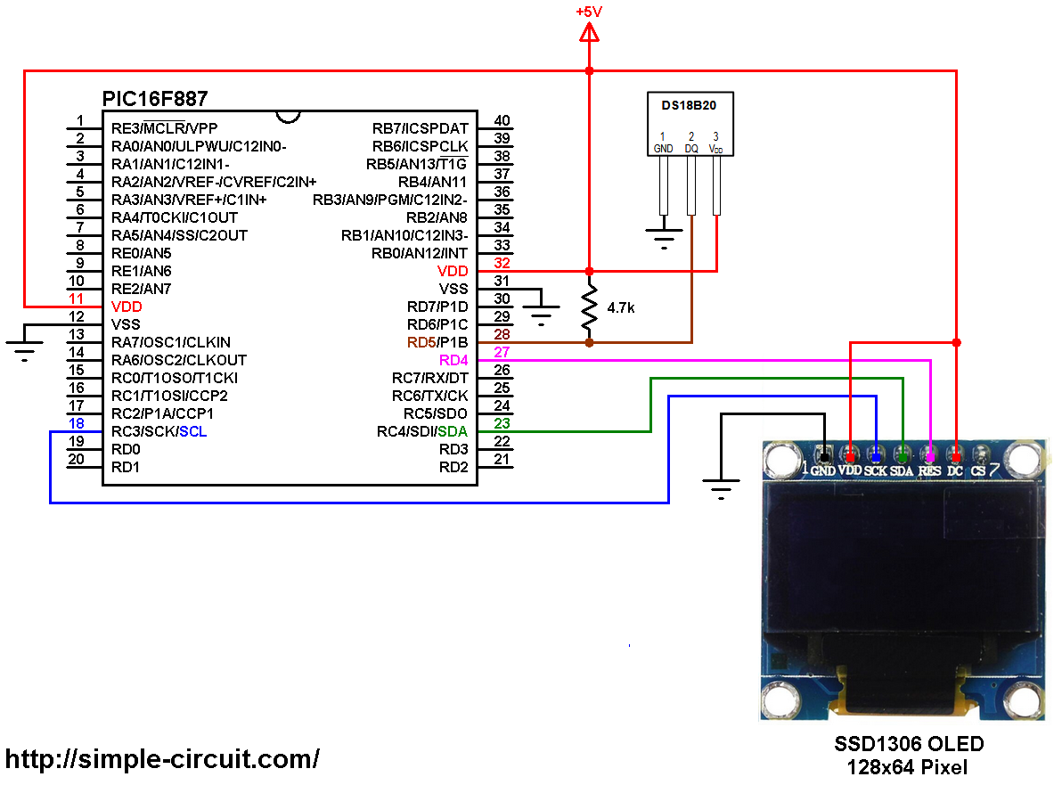
(All grounded terminals are connected together)
The PIC16F887 microcontroller has one hardware I2C module (MSSP module) with SDA on pin RC4 (#23) and SCL on pin RC3 (#18). The SDA pin of the MCU is connected to the SDA pin of the display and the SCL pin of the MCU is connected to the SCL pin of the display.
The reset pin of the display is connected to pin RD4 (#27) of the microcontroller.
The SSD1306 OLED display DC pin is connected to VDD which means the I2C slave address of the display is 0x7A (default address).
The DS18B20 sensor has 3 pins (from left to right): GND, data and VCC (+5V). The data pin is connected to PIC16F887 pin RD5.
In this project the PIC16F887 microcontroller runs with its internal oscillator @ 8 MHz, MCLR pin is configured as an input pin.
The C code:
The following C code is for mikroC PRO for PIC compiler, it was tested with version 7.2.0.
To be able to compile the C code below with no error, a driver (& library) for the SSD1306 OLED display is required, it’s full name is SSD1306.C, download link is below:
SSD1306 OLED display driver for mikroC compiler
after the download, add the driver file (SSD1306.C) to project folder.
MikroC PRO for PIC compiler has a built-in one-wire protocol library which makes the interfacing more easier.
The default resolution of DS18B20 is 12-bit which means the step of the temperature is 0.0625°C. The datasheet of the device contains more details about that. Rest of code is described through comments.
Full mikroC code:
Configuration words:
CONFIG1 = 0x2CD4
CONFIG2 = 0x0700
1 2 3 4 5 6 7 8 9 10 11 12 13 14 15 16 17 18 19 20 21 22 23 24 25 26 27 28 29 30 31 32 33 34 35 36 37 38 39 40 41 42 43 44 45 46 47 48 49 50 51 52 53 54 55 56 57 58 59 60 61 62 63 64 65 66 67 68 69 70 71 72 73 74 75 76 77 78 79 80 81 82 83 84 85 86 87 88 89 90 91 92 93 94 95 96 97 98 | /************************************************************************************** PIC16F887 microcontroller with SSD1306 OLED (128x64 Pixel) and DS18B20 temperature sensor. C Code for mikroC PRO for PIC compiler Internal oscillator used @ 8MHz Configuration words: CONFIG1 = 0x2CD4 CONFIG2 = 0x0700 This is a free software with NO WARRANTY. http://simple-circuit.com/ ***************************************************************************************/ // SSD1306 OLED reset pin definition (if available) #define SSD1306_RST RD4_bit #define SSD1306_RST_DIR TRISD4_bit // include SSD1306 OLED driver source code #include <SSD1306.c> // variable declarations int raw_temp; char *temp = "000.0000 C"; char degree[] = {0, 7, 5, 7, 0}; // degree symbol custom char // main function void main() { OSCCON = 0x70; // set internal oscillator to 8MHz delay_ms(1000); // wait a second I2C1_Init(400000); // initialize I2C communication with clock frequency of 400kHz // initialize the SSD1306 OLED with an I2C addr = 0x7A (default address) SSD1306_Init(SSD1306_SWITCHCAPVCC, SSD1306_I2C_ADDRESS); // clear the whole display SSD1306_ClearDisplay(); SSD1306_GotoXY(5, 2); // move cursor to column 5, row 2 SSD1306_Print("DS18B20 SENSOR"); SSD1306_GotoXY(6, 5); // move cursor to column 6, row 5 SSD1306_Print("TEMPERATURE:"); while(1) { Ow_Reset(&PORTD, 5); // onewire reset signal Ow_Write(&PORTD, 5, 0xCC); // issue command SKIP_ROM Ow_Write(&PORTD, 5, 0x44); // issue command CONVERT_T while (Ow_Read(&PORTD, 5) == 0) ; Ow_Reset(&PORTD, 5); // onewire reset signal Ow_Write(&PORTD, 5, 0xCC); // issue command SKIP_ROM Ow_Write(&PORTD, 5, 0xBE); // issue command READ_SCRATCHPAD raw_temp = Ow_Read(&PORTD, 5); // read temperature LSB byte raw_temp |= (Ow_Read(&PORTD, 5) << 8); // read temperature MSB byte if(raw_temp & 0x8000) // if the temperature is negative { temp[0] = '-'; // put minus sign (-) raw_temp = ~raw_temp + 1; // change temperature value to positive form } else { if((raw_temp >> 4) >= 100) // if the temperature >= 100 °C temp[0] = '1'; // put 1 of hundreds else // otherwise temp[0] = ' '; // put space ' ' } // put the first two digits (for tens and ones) temp[1] = ( (raw_temp >> 4) / 10 ) % 10 + '0'; // put tens digit temp[2] = (raw_temp >> 4) % 10 + '0'; // put ones digit // put the 4 fraction digits (digits after the point) // why 625: because we're working with 12-bit resolution temp[4] = ( (raw_temp & 0x0F) * 625) / 1000 + '0'; // put thousands digit temp[5] = (((raw_temp & 0x0F) * 625) / 100 ) % 10 + '0'; // put hundreds digit temp[6] = (((raw_temp & 0x0F) * 625) / 10 ) % 10 + '0'; // put tens digit temp[7] = ( (raw_temp & 0x0F) * 625) % 10 + '0'; // put ones digit // print the measured temperature SSD1306_GotoXY(6, 7); // move cursor to column 6, row 7 SSD1306_Print(temp); // display temperature SSD1306_GotoXY(14, 7); // move cursor to column 14, row 7 SSD1306_PutCustomC(degree); // degree symbol ( ° ) delay_ms(1000); // wait a second } } // end of code. |
The simulation of this project using Proteus should be similar to what’s shown in the following video where PIC16F877A microcontroller is used: