This PIC project shows how to implement a simple temperature measurement station (digital thermometer) using PIC18F46K22 microcontroller and DS18B20 temperature sensor.
The PIC18F46K22 MCU reads temperature from the DS18B20 sensor and print its value (in °C) on Nokia 5110 monochrome LCD display (84×48 pixel resolution).
MikroC PRO for PIC compiler is used in this project.
To see how to interface PIC18F46K22 MCU with Nokia 5110 LCD using mikroC, visit this post:
Interfacing PIC MCU with Nokia 5110 LCD | mikroC Projects
About the DS18B20 sensor:
The DS18B20 sensor is a 3-pin electronic component (like a simple transistor) from Maxim (formerly Dallas) which uses 1-wire protocol to communicate with master device (microprocessor, microcontroller ….). Each DS18B20 device has a unique 64-bit serial code, which allows multiple DS18B20s to function on the same 1-Wire bus and controlled with one master device.
The DS18B20 sensor provides 9-bit to 12-bit Celsius temperature measurement resolution (programmable resolution).
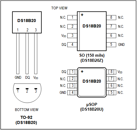
The DS18B20 sensor is available in 8-Pin SO (150 mils), 8-Pin μSOP, and 3-Pin TO-92 Packages. DS18B20 pin configurations is shown below:
Hardware Required:
- PIC18F46K22 microcontroller —-> datasheet
- Nokia 5110 LCD module
- DS18B20 temperature sensor —-> datasheet
- AMS1117 3V3 voltage regulator
- 10 uF capacitor
- 100 nF ceramic capacitor
- 5 x 3.3k ohm resistor
- 5 x 2.2k ohm resistor
- 4.7k ohm resistor
- 5V source
- Breadboard
- Jumper wires
PIC18F46K22 with Nokia 5110 LCD and DS18B20 sensor circuit:
The image below shows project circuit diagram.
The DS18B20 temperature sensor has 3 pins (from left to right): GND, data and VCC where:
GND is connected to circuit ground (0V),
Data pin is connected to pin RB0 (#33) of the PIC18F46K22,
VCC is connected to +5V.
The 4.7k ohm resistor is required because the DS18B20 output is open drain.

All the grounded terminals are connected together.
The Nokia 5110 which is shown in the circuit diagram has 8 pins (from left to right): RST (reset), CE (chip enable), DC (or D/C: data/command), Din (data in), Clk (clock), VCC (3.3V), BL (back light) and Gnd (ground).
The Nokia 5110 LCD works with 3.3V only (power supply and control lines). The LCD module is supplied with 3.3V which comes from the AMS1117 3V3 voltage regulator, this regulator steps down the 5V into 3.3V (supplies the LCD controller PCD8544 with regulated 3V3).
All PIC18F46K22 microcontroller output pins are 5V, connecting a 5V pin directly to the Nokia 5110 LCD may damage its controller circuit!
To connect the PIC18F46K22 to the LCD module, I used voltage divider for each line. That means there are 5 voltage dividers. Each voltage divider consists of 2.2k and 3.3k resistors, this drops the 5V into 3V which is sufficient.
So, the Nokia 5110 LCD pins are connected to PIC18F46K22 MCU as follows (each one through voltage divider):
RST (reset) pin is connected to pin RD0 (#19)
CE (chip enable) pin is connected to pin RD1 (#20)
DC (data/command) pin is connected to pin RD2 (#21)
DIN (data in) pin is connected to pin RD3 (#22)
CLK (clock) pin is connected to pin RD4 (#27)
VCC and BL are connected to AMS1117 3V3 regulator output pin and GND is connected to circuit ground (0V).
In this project the PIC18F46K22 microcontroller runs with its internal oscillator @ 16 MHz, MCLR pin is configured as an input pin.
PIC18F46K22 with DS18B20 sensor and Nokia 5110 LCD C code:
The following C code is for mikroC PRO for PIC compiler, it was tested with version 7.2.0.
To be able to compile project C code, a driver for the Nokia 5110 LCD is required, download link is below. After you download the driver file which named NOKIA5110.C, add it to your project folder:
Nokia 5110 LCD library for mikroC compiler
The connection of the LCD pins with the microcontroller are defined in the C code as shown below:
1 2 3 4 5 6 7 8 | // Nokia 5110 LCD module connections // use software SPI #define LCD_RST RD0_bit // reset pin, optional! #define LCD_CS RD1_bit // chip select pin, optional! #define LCD_DC RD2_bit // data/command pin #define LCD_DAT RD3_bit // data-in pin (MOSI) #define LCD_CLK RD4_bit // clock pin // end LCD module connections |
Function used in the C code:
unsigned int ds18b20_read(): reads temperature from the DS18B20 sensor, returns the value of the temperature as unsigned 16-bit number.
The resolution of this thermometer is 0.0625°C.
Rest of code is described through comments.
Full mikroC code:
1 2 3 4 5 6 7 8 9 10 11 12 13 14 15 16 17 18 19 20 21 22 23 24 25 26 27 28 29 30 31 32 33 34 35 36 37 38 39 40 41 42 43 44 45 46 47 48 49 50 51 52 53 54 55 56 57 58 59 60 61 62 63 64 65 66 67 68 69 70 71 72 73 74 75 76 77 78 79 80 81 82 83 84 85 86 87 88 89 90 91 92 93 94 95 96 97 98 99 100 101 | /************************************************************************************** Digital thermometer using PIC18F4550 microcontroller, DS18B20 temperature sensor and Nokia 5110 LCD. C Code for mikroC PRO for PIC compiler. Internal oscillator used @ 16MHz Configuration words: CONFIG1H = 0x0028 CONFIG2L = 0x0018 CONFIG2H = 0x003C CONFIG3H = 0x0037 CONFIG4L = 0x0081 CONFIG5L = 0x000F CONFIG5H = 0x00C0 CONFIG6L = 0x000F CONFIG6H = 0x00E0 CONFIG7L = 0x000F CONFIG7H = 0x0040 This is a free software with NO WARRANTY. http://simple-circuit.com/ ***************************************************************************************/ // Nokia 5110 LCD module connections // use software SPI #define LCD_RST RD0_bit // reset pin, optional! #define LCD_CS RD1_bit // chip select pin, optional! #define LCD_DC RD2_bit // data/command pin #define LCD_DAT RD3_bit // data-in pin (MOSI) #define LCD_CLK RD4_bit // clock pin // end LCD module connections // include Nokia 5110 LCD driver source file #include <NOKIA5110.c> /// read raw temperature from DS18B20 sensor unsigned int ds18b20_read() { unsigned int _temp; Ow_Reset(&PORTB, 0); // onewire reset signal Ow_Write(&PORTB, 0, 0xCC); // issue command SKIP_ROM Ow_Write(&PORTB, 0, 0x44); // issue command CONVERT_T while (Ow_Read(&PORTB, 0) == 0) ; Ow_Reset(&PORTB, 0); // onewire reset signal Ow_Write(&PORTB, 0, 0xCC); // issue command SKIP_ROM Ow_Write(&PORTB, 0, 0xBE); // issue command READ_SCRATCHPAD _temp = Ow_Read(&PORTB, 0); // read temperature LSB byte _temp |= (Ow_Read(&PORTB, 0) << 8); // read temperature MSB byte return _temp; } // main function void main() { OSCCON = 0x70; // set internal oscillator to 16MHz ANSELB = 0; // configure all PORTB pins as digital ANSELD = 0; // configure all PORTD pins as digital TRISD = 0; // configure all PORTD pins as outputs LCD_Begin(); // initialize the LCD LCD_Clear(); // clear the display buffer LCD_SetContrast(60); // set LCD contrast LCD_GotoXY(3, 4); // move cursor to position (3, 4) pixel LCD_Print("PIC18F46K22 +"); LCD_GotoXY(0, 14); // move cursor to position (0, 14) pixel LCD_Print("DS18B20 SENSOR"); LCD_GotoXY(7, 27); // move cursor to position (7, 27) pixel LCD_Print("TEMPERATURE:"); LCD_Display(); // update the screen while(1) { unsigned int ds18b20_temp; char buffer[11]; ds18b20_temp = ds18b20_read(); // read temperature from DS18B20 sensor if (ds18b20_temp & 0x8000) // if temperature < 0 { ds18b20_temp = ~ds18b20_temp + 1; // change temperature value to positive form sprinti(buffer, "-%02u.%04u C", (ds18b20_temp/16) % 100, (ds18b20_temp & 0x0F) * 625); } else { // otherwise (temperature >= 0) if (ds18b20_temp/16 > 100) // if temperature >= 100 °C sprinti(buffer, "%03u.%04u C", ds18b20_temp/16, (ds18b20_temp & 0x0F) * 625); else // otherwise ( 0 <= temperature < 100) sprinti(buffer, " %02u.%04u C", ds18b20_temp/16, (ds18b20_temp & 0x0F) * 625); } LCD_GotoXY(9, 37); LCD_Print(buffer); LCD_DrawRect(59, 37, 3, 3, BLACK); // print degree symbol ( ° ) LCD_Display(); // update the screen delay_ms(1000); // wait a second } } // end of code. |
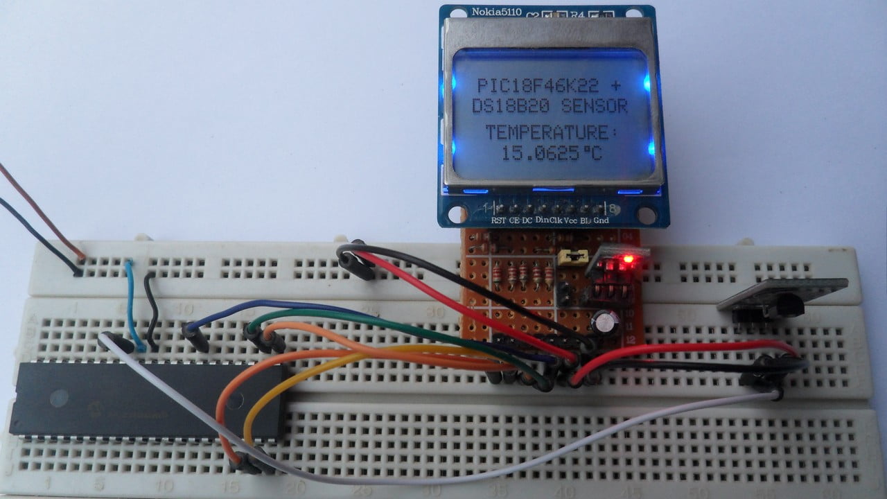
The following picture shows my protoboard circuit:
Cannot understand why dont supply all with 3.3v, 18f46k22 work from 2v to 5v ds18b20 also, from 3v to 5v and display work to 3.3v, you use a resistive divisor when is not needed if use AMS1117 regulator 3.3v 1100ma.