This project shows how to build a real time clock using PIC16F887 microcontroller and DS1307 RTC (or DS3231) chip where time and date are displayed on OLED display with SSD1306 controller (128×64 Pixel).
With the help of a 3V coin cell battery the DS1307 keeps the time running even if the main power source is cut.
The compiler used in this project is mikroElektronika mikroC PRO for PIC.
A small video shows Proteus simulation of this project at the end of the post.
The SSD1306 OLED used in this project is configured to work in I2C mode, some SSD1306 OLED boards may require a small hardware modifications (to select between SPI mode and I2C mode) such as soldering, placing jumpers …
To simplify project circuit, the SSD1306 OLED display and the DS1307 RTC chip share the same I2C bus, always the PIC16F887 microcontroller talks with one device only because their I2C slave addresses are different.
Related Projects:
Interfacing PIC microcontroller with SSD1306 OLED | mikroC Projects
Hardware Required:
- PIC16F887 microcontroller
- SSD1306 OLED display (128×64 Pixel)
- DS1307 RTC —-> datasheet
- 32.768KHz crystal oscillator
- 2 x 10k ohm resistor
- 2 x push button
- 3V coin cell battery
- 5V power source
- Breadboard
- Jumper wires
PIC16F887 Interfacing with SSD1306 and DS1307 circuit:
Project circuit schematic diagram is shown below.
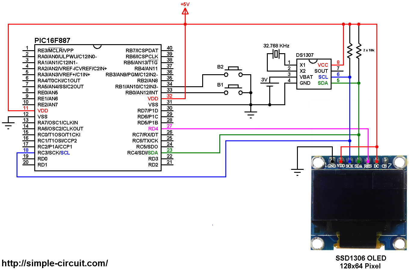
(All grounded terminals are connected together)
The PIC16F887 microcontroller has one hardware I2C module (MSSP module) with SDA on pin RC4 (#23) and SCL on pin RC3 (#18). The SDA pin of the MCU is connected to the SDA pin of the display (& DS1307 RTC) and the SCL pin of the MCU is connected to the SCL pin of the display (& DS1307 RTC).
The reset pin of the display is connected to pin RD4 (#27) of the microcontroller.
The SSD1306 OLED display DC pin is connected to VDD which means the I2C slave address of the display is 0x7A.
The two push buttons B1 and B2 are for setting time and date. Button B1 is connected to pin RB0 (#33) and B2 is connected to pin RB1 (#34). Internal pull-ups for RB0 and RB1 pins are enabled in the code.
In this project the PIC16F887 microcontroller runs with its internal oscillator @ 8 MHz, MCLR pin is configured as an input pin.
PIC16F887 Interfacing with SSD1306 and DS1307 C code:
The following C code is for mikroC PRO for PIC compiler, it was tested with version 7.2.0.
To be able to compile the C code below with no error, a driver (& library) for the SSD1306 OLED display is required, it’s full name is SSD1306.C, download link is below:
SSD1306 OLED display driver for mikroC compiler
after the download, add the driver file (SSD1306.C) to project folder.
The DS1307 RTC and the SSD1306 OLED display share the same I2C bus, DS1307 I2C address is 0xD0 and SSD1306 display I2C address is 0x7A (default address).
The reset pin of the SSD1306 OLED display module is connected to pin RD4 of the microcontroller, this connection is defined as (there is no need for this connection if the display board has no rest pin):
1 2 3 | // SSD1306 OLED reset pin definition (if available) #define SSD1306_RST RD4_bit #define SSD1306_RST_DIR TRISD4_bit |
Full mikroC code:
Configuration words:
CONFIG1 = 0x2CD4
CONFIG2 = 0x0700
1 2 3 4 5 6 7 8 9 10 11 12 13 14 15 16 17 18 19 20 21 22 23 24 25 26 27 28 29 30 31 32 33 34 35 36 37 38 39 40 41 42 43 44 45 46 47 48 49 50 51 52 53 54 55 56 57 58 59 60 61 62 63 64 65 66 67 68 69 70 71 72 73 74 75 76 77 78 79 80 81 82 83 84 85 86 87 88 89 90 91 92 93 94 95 96 97 98 99 100 101 102 103 104 105 106 107 108 109 110 111 112 113 114 115 116 117 118 119 120 121 122 123 124 125 126 127 128 129 130 131 132 133 134 135 136 137 138 139 140 141 142 143 144 145 146 147 148 149 150 151 152 153 154 155 156 157 158 159 160 161 162 163 164 165 166 167 168 169 170 171 172 173 174 175 176 177 178 179 180 181 182 183 184 185 186 187 188 189 190 191 192 193 194 195 196 197 198 199 200 201 202 203 204 205 206 207 208 209 210 211 212 213 214 215 216 217 218 219 220 221 222 223 224 225 226 227 228 229 230 231 232 233 234 235 236 237 238 239 240 241 242 243 244 245 246 247 248 249 250 251 252 253 254 255 256 257 258 259 260 261 262 263 264 265 266 267 | /************************************************************************************** Real time clock using PIC16F887 microcontroller, SSD1306 OLED display (128x64 Pixel) and RTC chip (DS1307, DS3231, DS3232...) C Code for mikroC PRO for PIC compiler Internal oscillator used @ 8MHz Configuration words: CONFIG1 = 0x2CD4 CONFIG2 = 0x0700 This is a free software with NO WARRANTY. http://simple-circuit.com/ ***************************************************************************************/ // SSD1306 OLED reset pin definition (if available) #define SSD1306_RST RD4_bit #define SSD1306_RST_DIR TRISD4_bit // button definitions #define button1 RB0_bit // button B1 is connected to RB0 pin #define button2 RB1_bit // button B2 is connected to RB1 pin // include SSD1306 OLED driver source code #include <SSD1306.c> // Variables declaration char Time[] = " : : "; char Date[] = " / /20 "; unsigned short i, second, minute, hour, w_day, day, month, year; // a small function for button1 (B1) debounce char debounce () { char i, count = 0; for(i = 0; i < 5; i++) { if (button1 == 0) count++; delay_ms(10); } if(count > 2) return 1; else return 0; } // function for display day of the week void display_day() { SSD1306_GotoXY(7, 1); switch(w_day){ case 1: SSD1306_Print(" SUNDAY "); break; case 2: SSD1306_Print(" MONDAY "); break; case 3: SSD1306_Print(" TUESDAY "); break; case 4: SSD1306_Print("WEDNESDAY"); break; case 5: SSD1306_Print("THURSDAY "); break; case 6: SSD1306_Print(" FRIDAY "); break; default: SSD1306_Print("SATURDAY "); } } void RTC_Display() { // convert BCD to decimal second = (second >> 4) * 10 + (second & 0x0F); minute = (minute >> 4) * 10 + (minute & 0x0F); hour = (hour >> 4) * 10 + (hour & 0x0F); day = (day >> 4) * 10 + (day & 0x0F); month = (month >> 4) * 10 + (month & 0x0F); year = (year >> 4) * 10 + (year & 0x0F); // end conversion // update time array Time[7] = second % 10 + '0'; Time[6] = second / 10 + '0'; Time[4] = minute % 10 + '0'; Time[3] = minute / 10 + '0'; Time[1] = hour % 10 + '0'; Time[0] = hour / 10 + '0'; // update date array Date[9] = year % 10 + '0'; Date[8] = year / 10 + '0'; Date[4] = month % 10 + '0'; Date[3] = month / 10 + '0'; Date[1] = day % 10 + '0'; Date[0] = day / 10 + '0'; // print date SSD1306_GotoXY(6, 3); SSD1306_Print(Date); // print time SSD1306_GotoXY(7, 8); SSD1306_Print(Time); } // make 'editing' parameter blinks function void blink() { char j = 0; while(j < 100 && button1 && button2) { j++; delay_ms(5); } } // edit time and date function char edit(char x_pos, char y_pos, char parameter) { while(debounce()); // call debounce function (wait for B1 to be released) while(1) { while(!button2) // if button B2 is pressed { parameter++; if(i == 0 && parameter > 31) // if date > 31 ==> date = 1 parameter = 1; if(i == 1 && parameter > 12) // if month > 12 ==> month = 1 parameter = 1; if(i == 2 && parameter > 99) // if year > 99 ==> year = 0 parameter = 0; if(i == 3 && parameter > 23) // if hours > 23 ==> hours = 0 parameter = 0; if(i == 4 && parameter > 59) // if minutes > 59 ==> minutes = 0 parameter = 0; SSD1306_GotoXY(x_pos, y_pos); SSD1306_PutC(parameter / 10 + '0'); SSD1306_PutC(parameter % 10 + '0'); delay_ms(200); // wait 200ms } SSD1306_GotoXY(x_pos, y_pos); SSD1306_Print(" "); blink(); SSD1306_GotoXY(x_pos, y_pos); SSD1306_PutC(parameter / 10 + '0'); SSD1306_PutC(parameter % 10 + '0'); blink(); if(!button1) // if button B1 is pressed if(debounce()) // call debounce function (make sure if B1 is pressed) { i++; // increment 'i' for the next parameter return parameter; // return parameter value and exit } } } // main function void main() { OSCCON = 0x70; // set internal oscillator to 8MHz ANSELH = 0; // configure all PORTB pins as digital // enable RB0 and RB1 internal pull ups NOT_RBPU_bit = 0; // clear RBPU bit (OPTION_REG.7) WPUB = 0x03; // WPUB register = 0b00000011 delay_ms(1000); // wait a second I2C1_Init(100000); // initialize I2C communication with clock frequency of 100KHz // initialize the SSD1306 OLED with an I2C addr = 0x7A (default address) SSD1306_Init(SSD1306_SWITCHCAPVCC, SSD1306_I2C_ADDRESS); // clear the whole display SSD1306_ClearDisplay(); SSD1306_GotoXY(9, 6); SSD1306_Print("TIME:"); while(1) { if(!button1) // if button B1 is pressed if(debounce()) // call debounce function (make sure if B1 is pressed) { i = 0; while(debounce()); // call debounce function (wait for button B1 to be released) while(1) { while(!button2) // while button B2 pressed { w_day++; // increment w_day if(w_day > 7) w_day = 1; display_day(); // call display_day function delay_ms(200); // wait 200 ms } SSD1306_GotoXY(7, 1); SSD1306_Print(" "); blink(); // call blink function display_day(); // call display_day function blink(); // call blink function if(!button1) // if button B1 is pressed break; } day = edit(6, 3, day); // edit date month = edit(9, 3, month); // edit month year = edit(14, 3, year); // edit year hour = edit(7, 8, hour); // edit hours minute = edit(10, 8, minute); // edit minutes // convert decimal to BCD minute = ((minute / 10) << 4) + (minute % 10); hour = ((hour / 10) << 4) + (hour % 10); day = ((day / 10) << 4) + (day % 10); month = ((month / 10) << 4) + (month % 10); year = ((year / 10) << 4) + (year % 10); // end conversion while(debounce()); // call debounce function (wait for button B1 to be released) // write data to RTC chip I2C1_Start(); // start I2C I2C1_Wr(0xD0); // RTC chip address I2C1_Wr(0); // send register address I2C1_Wr(0); // reset seconds and start oscillator I2C1_Wr(minute); // write minute value to RTC chip I2C1_Wr(hour); // write hour value to RTC chip I2C1_Wr(w_day); // write day value (not used) I2C1_Wr(day); // write date value to RTC chip I2C1_Wr(month); // write month value to RTC chip I2C1_Wr(year); // write year value to RTC chip I2C1_Stop(); // stop I2C delay_ms(200); // wait 200ms } // read current time and date from the RTC chip I2C1_Start(); // start I2C I2C1_Wr(0xD0); // RTC chip address I2C1_Wr(0); // send register address I2C1_Repeated_Start(); // restart I2C I2C1_Wr(0xD1); // initialize data read second = I2C1_Rd(1); // read seconds from register 0 minute = I2C1_Rd(1); // read minutes from register 1 hour = I2C1_Rd(1); // read hour from register 2 w_day = I2C1_Rd(1); // read day from register 3 (not used) day = I2C1_Rd(1); // read date from register 4 month = I2C1_Rd(1); // read month from register 5 year = I2C1_Rd(0); // read year from register 6 I2C1_Stop(); // stop I2C display_day(); // print day of the week RTC_Display(); // print time & date delay_ms(50); // wait 50 ms } } // end of code. |
The simulation of this project using Proteus should be similar to what’s shown in the following video where PIC16F877A microcontroller is used:
Hi.
I would like to know if there is a way to change the size of the text in this library for the oled screen
Font size cannot be changed in this library. This library is for MCUs with limited RAM like the PIC16F887.
If you want more features for the SSD1306 OLED display, this post may help you:
PIC MCU with SSD1306 OLED – I2C Mode Example | mikroC Projects