Interfacing LCD displays with a PIC microcontroller using CCS C compiler needs at least 7 data pins (using the built-in LCD driver). Number of pins needed for the LCD can be reduced to 2 by using an I2C I/O (Input/Output) expander like PCF8574 or PCF8574A. Adding the I2C I/O expander builds an I2C LCD. The I2C LCD is connected with the microcontroller via 2 lines: SDA (serial data) and SCL (serial clock). I2C = IIC = Inter-Integrated Circuit.
This post shows how to interface PIC microcontroller with I2C LCD using CCS C compiler where a driver (library) will be used to simplify the interfacing source codes for further project.
This driver works also with DFRobot I2C LCD displays since they’ve the same main circuit connections.
Interfacing PIC microcontroller with I2C LCD circuit:
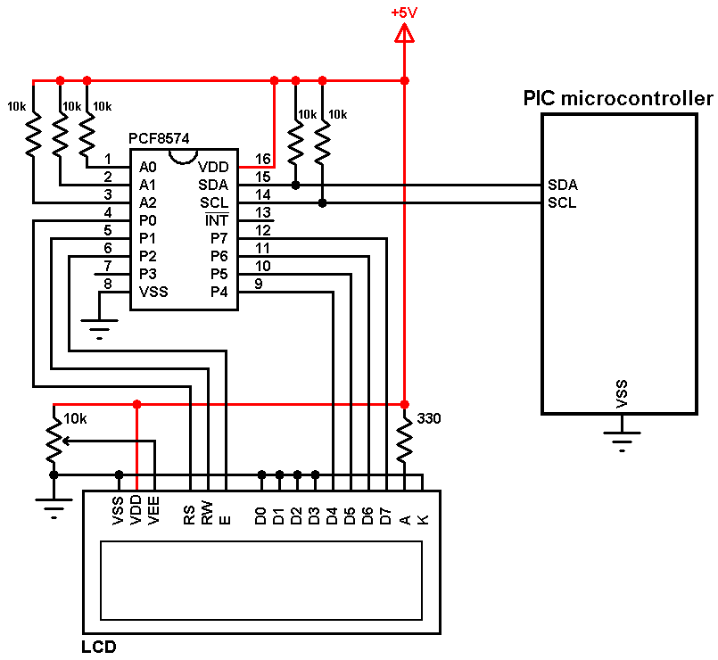
(All grounded terminals are connected together)
The main component of the I2C LCD display is the PCF8574 I/O expander, with only two pins SDA and SCL we get a maximum of 8 pins from P0 to P7. PCF8574A also can be used but it has a different address.
All LCD data pins are connected to the PCF8574 where: RS, RW, E, D4, D5, D6 and D7 are connected to P0, P1, P2, P4, P5, P6 and P7 respectively.
PCF8574 I/O expander SDA and SCL pins are connected to the PIC microcontroller SDA and SCL pins respectively.
PCF8574 I/O expander A0, A1 and A2 pins are the address pins which decide the I2C address of the chip. In this example each pin is connected to +5V through a 10k ohm resistor (the 10k resistor is optional, each pin can be connected directly to +5V).
The I2C address of the PCF8574 is: 0 1 0 0 A2 A1 A0 0
In the circuit shown above A2, A1 and A0 are connected to +5V (through 10k resistors) which means the I2C address is equal to 0x4E.
If the PCF8574A is used instead of the PCF8574 the I2C address is: 0 1 1 1 A2 A1 A0 0 = 0x7E.
The LCD and the PCF8574 are supplied with 5V.
Note that PCF8574T is the same as PCF8574 and PCF8574AT is the same as PCF8574A.
I2C LCD driver for CCS PIC C compiler:
Driver source code is below which can be downloaded from the link below.
I2C LCD driver download
User functions:
LCD_Begin(unsigned int8 _i2c_addr); // Must be called before any other function, _i2c_addr is the I2C I/O expander address, for example 0x27.
LCD_Goto(unsigned int8 col, unsigned int8 row); // Set write position on LCD (upper left is 1,1 and second row first position is 1,2)
LCD_Out(unsigned int8 LCD_Char); // Display Char on the LCD
LCD_Cmd(unsigned int8 Command); // Send a command to the LCD
The following commands can be used with LCD_Com function (example: LCD_Com(LCD_CLEAR);):
| Command | Description |
| LCD_FIRST_ROW | Move cursor to the 1st row |
| LCD_SECOND_ROW | Move cursor to the 2nd row |
| LCD_THIRD_ROW | Move cursor to the 3rd row |
| LCD_FOURTH_ROW | Move cursor to the 4th row |
| LCD_CLEAR | Clear display |
| LCD_RETURN_HOME | Return cursor to home position, returns a shifted display to its original position. Display data RAM is unaffected |
| LCD_CURSOR_OFF | Turn off cursor |
| LCD_UNDERLINE_ON | Underline cursor on |
| LCD_BLINK_CURSOR_ON | Blink cursor on |
| LCD_MOVE_CURSOR_LEFT | Move cursor left without changing display data RAM |
| LCD_MOVE_CURSOR_RIGHT | Move cursor right without changing display data RAM |
| LCD_TURN_ON | Turn Lcd display on |
| LCD_TURN_OFF | Turn Lcd display off |
| LCD_SHIFT_LEFT | Shift display left without changing display data RAM |
| LCD_SHIFT_RIGHT | Shift display right without changing display data RAM |
Driver source code:
1 2 3 4 5 6 7 8 9 10 11 12 13 14 15 16 17 18 19 20 21 22 23 24 25 26 27 28 29 30 31 32 33 34 35 36 37 38 39 40 41 42 43 44 45 46 47 48 49 50 51 52 53 54 55 56 57 58 59 60 61 62 63 64 65 66 67 68 69 70 71 72 73 74 75 76 77 78 79 80 81 82 83 84 85 86 87 88 89 90 91 92 93 94 95 96 97 98 99 100 101 102 103 104 105 106 107 108 109 110 111 112 113 114 115 116 | // CCS C driver code for I2C LCDs (HD44780 compliant controllers) // http://simple-circuit.com/ #define LCD_BACKLIGHT 0x08 #define LCD_NOBACKLIGHT 0x00 #define LCD_FIRST_ROW 0x80 #define LCD_SECOND_ROW 0xC0 #define LCD_THIRD_ROW 0x94 #define LCD_FOURTH_ROW 0xD4 #define LCD_CLEAR 0x01 #define LCD_RETURN_HOME 0x02 #define LCD_ENTRY_MODE_SET 0x04 #define LCD_CURSOR_OFF 0x0C #define LCD_UNDERLINE_ON 0x0E #define LCD_BLINK_CURSOR_ON 0x0F #define LCD_MOVE_CURSOR_LEFT 0x10 #define LCD_MOVE_CURSOR_RIGHT 0x14 #define LCD_TURN_ON 0x0C #define LCD_TURN_OFF 0x08 #define LCD_SHIFT_LEFT 0x18 #define LCD_SHIFT_RIGHT 0x1E #ifndef LCD_TYPE #define LCD_TYPE 2 // 0=5x7, 1=5x10, 2=2 lines #endif int1 RS; unsigned int8 i2c_addr, backlight_val = LCD_BACKLIGHT; void LCD_Write_Nibble(unsigned int8 n); void LCD_Cmd(unsigned int8 Command); void LCD_Goto(unsigned int8 col, unsigned int8 row); void LCD_Out(unsigned int8 LCD_Char); void LCD_Begin(unsigned int8 _i2c_addr); void Backlight(); void noBacklight(); void Expander_Write(unsigned int8 value); void LCD_Write_Nibble(unsigned int8 n) { n |= RS; Expander_Write(n); Expander_Write(n | 0x04); delay_us(1); Expander_Write(n & 0xFB); delay_us(50); } void LCD_Cmd(unsigned int8 Command) { RS = 0; LCD_Write_Nibble(Command & 0xF0); LCD_Write_Nibble((Command << 4) & 0xF0); } void LCD_Goto(unsigned int8 col, unsigned int8 row) { switch(row) { case 2: LCD_Cmd(0xC0 + col-1); break; case 3: LCD_Cmd(0x94 + col-1); break; case 4: LCD_Cmd(0xD4 + col-1); break; default: // case 1: LCD_Cmd(0x80 + col-1); } } void LCD_Out(unsigned int8 LCD_Char){ RS = 1; LCD_Write_Nibble(LCD_Char & 0xF0); LCD_Write_Nibble((LCD_Char << 4) & 0xF0); } void LCD_Begin(unsigned int8 _i2c_addr) { i2c_addr = _i2c_addr; Expander_Write(0); delay_ms(40); LCD_Cmd(3); delay_ms(5); LCD_Cmd(3); delay_ms(5); LCD_Cmd(3); delay_ms(5); LCD_Cmd(LCD_RETURN_HOME); delay_ms(5); LCD_Cmd(0x20 | (LCD_TYPE << 2)); delay_ms(50); LCD_Cmd(LCD_TURN_ON); delay_ms(50); LCD_Cmd(LCD_CLEAR); delay_ms(50); LCD_Cmd(LCD_ENTRY_MODE_SET | LCD_RETURN_HOME); delay_ms(50); } void Backlight() { backlight_val = LCD_BACKLIGHT; Expander_Write(0); } void noBacklight() { backlight_val = LCD_NOBACKLIGHT; Expander_Write(0); } void Expander_Write(unsigned int8 value) { I2C_Start(I2C_LCD); I2C_Write(I2C_LCD, i2c_addr); I2C_Write(I2C_LCD, value | backlight_val); I2C_Stop(I2C_LCD); } |
Examples:
Interfacing PIC12F1822 microcontroller with I2C LCD
Thanks a lot, great work.
Proteus give me the following error:
[PIC16 CORE] PC=0x003D. Indirect write of 0x04 to address 0x0000 is itself an indirect write. [U1]
[PIC16 CORE] PC=0x0040. Indirect write of 0x00 to address 0x0000 is itself an indirect write. [U1]
[PIC16 CORE] PC=0x0043. Indirect write of 0x00 to address 0x0000 is itself an indirect write. [U1]
[PIC16 CORE] PC=0x001B. Indirect write of 0x00 to address 0x0000 is itself an indirect write. [U1]
[PIC16 CORE] PC=0x0022. Indirect write of 0x00 to address 0x0000 is itself an indirect write. [U1]
[PIC16 CORE] PC=0x0023. Indirect write of 0x04 to address 0x0000 is itself an indirect write. [U1]
This is the circuit:
https://ibb.co/fUNSZK
Also tested in real circuit, same result.
Well, code is ok, no errors, but for some reason, no data from SDA and SCL… Help plz! Code:
#include {16f877a.h} // replace {
#device *=16 ADC=10 ICD=true
#fuses noprotect, nowdt, xt, nolvp
#use delay (clock=4000000) //Fosc=4Mhz
#use i2c(master,SDA=23,SCL=18,FORCE_HW,STREAM=I2C_LCD)
#include {I2C_LCD.c} // replace {
void main() {
unsigned int8 i = 0;
//setup_oscillator(OSC_4MHZ); // Set internal oscillator to 8MHz
LCD_Begin(0x27); // Initialize LCD module with I2C address = 0x4E
LCD_Goto(2, 1); // Go to column 2 row 1
LCD_Out(“Hello, world!”);
while(TRUE) {
lcd_goto(7, 2); // Go to column 7 row 2
printf(lcd_out, “%03u”, i++); // Print i with 3 numbers max
delay_ms(500);
}
}
SOLVED: I removed the library from Source files and Voila! Problem solved! Thanks again!
Question, I cannot make this to work with pic16f877a:
#include
#fuses XT, NOWDT, NOPROTECT, BROWNOUT, PUT, NOLVP
#use delay(clock=4000000)
#use I2C(MASTER, SCL= 18, SDA=23,FORCE_HW,SLOW)
#include
//===========================
void main()
{
int8 c;
while(1);
}
I get error:
Clean: Deleting intermediary and output files.
Clean: Deleted file “test.ESYM”.
Clean Warning: File “D:\PICC Proyectos\kk\test.o” doesn’t exist.
Clean: Deleted file “test.ERR”.
Clean: Done.
Executing: “C:\Program Files (x86)\PICC\Ccsc.exe” +FM “test.c” +DF +LN +T +A +M +Z +Y=9 +EA
*** Error 12 “D:\PICC Proyectos\kk\I2C_LCD.c” Line 112(13,20): Undefined identifier I2C_LCD
*** Error 12 “D:\PICC Proyectos\kk\I2C_LCD.c” Line 113(13,20): Undefined identifier I2C_LCD
*** Error 12 “D:\PICC Proyectos\kk\I2C_LCD.c” Line 114(13,20): Undefined identifier I2C_LCD
*** Error 12 “D:\PICC Proyectos\kk\I2C_LCD.c” Line 115(12,19): Undefined identifier I2C_LCD
4 Errors, 0 Warnings.
Halting build on first failure as requested.
BUILD FAILED: Thu Oct 04 00:36:14 2018
Any suggestions to make it work?
You’ve to add the I2C stream to #use I2C (STREAM=I2C_LCD), so it becomes:
#use I2C(MASTER, SCL= 18, SDA=23,FORCE_HW,SLOW,STREAM=I2C_LCD)
Thanks, now I have only 1 error, instead the 4 I had. It’s this:
Executing: “C:\Program Files (x86)\PICC\Ccsc.exe” +FM “LCD_prog_877A.c” +EXPORT +DF +LN +T +A +M +Z +Y=9 +EA
D:\PICC Proyectos\lcdi2c\LCD_prog_877A.o ===> 0 Errors, 0 Warnings.
Executing: “C:\Program Files (x86)\PICC\Ccsc.exe” +FM “I2C_LCD.c” +EXPORT +DF +LN +T +A +M +Z +Y=9 +EA
*** Error 128 “D:\PICC Proyectos\lcdi2c\I2C_LCD.c” Line 29(1,2): A #DEVICE required before this line
D:\PICC Proyectos\lcdi2c\I2C_LCD.o ===> 1 Errors, 0 Warnings.
Halting build on first failure as requested.
BUILD FAILED: Thu Oct 04 14:52:39 2018
It’s in the I2C_LCD.c library, line 29, instruction:
int1 RS;
Thanks again.