Interfacing LCD display with PIC microcontroller requires at least 6 data pins (for LCD pins: RS, E, D4, D5, D6 and D7). Number of pins needed for the LCD can be reduced to 2 by using an I2C I/O (Input/Output) expander like PCF8574 or PCF8574A. Adding the I2C I/O expander builds an I2C LCD. The I2C LCD is connected with the microcontroller via 2 lines: SDA (serial data) and SCL (serial clock). I2C = IIC = Inter-Integrated Circuit.
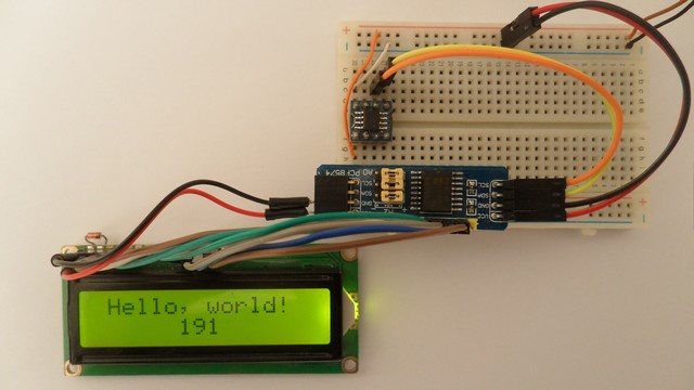
This small post shows an example for connecting LCD (with HD44780 or complaint controller) with Microchip PIC12F1822 8-bit microcontroller, this microcontroller has only 8 pins of which 5 can be used as outputs, therefore an I2C LCD is required.
This project works also with DFRobot I2C LCD displays.
The compiler used in this project is mikroElektronika mikroC PRO for PIC. An I2C LCD driver for mikroC PRO for PIC compiler is required to simplify example C code. This driver is just a C file named (with extension) I2C_LCD.c, we’ve to add this file to project folder, download link is below:
I2C LCD driver for mikroC PRO for PIC compiler
Related Project:
PIC MCU with I2C LCD and DS3231/DS1307 RTC | mikroC Projects
Hardware Required:
The components listed below are required for this project.
- PIC12F1822 microcontroller —-> datasheet
- LCD screen (16×2, 20×4 …)
- PCF8574 I/O expander (or PCF8574A) —-> PCF8574 datasheet
- 5 x 10k ohm resistor
- 330 ohm resistor
- 10k ohm variable resistor or potentiometer
- 5V source
- Breadboard
- Jumper wires
Interfacing PIC12F1822 microcontroller with I2C LCD circuit:
Example circuit schematic diagram is shown in the image below.
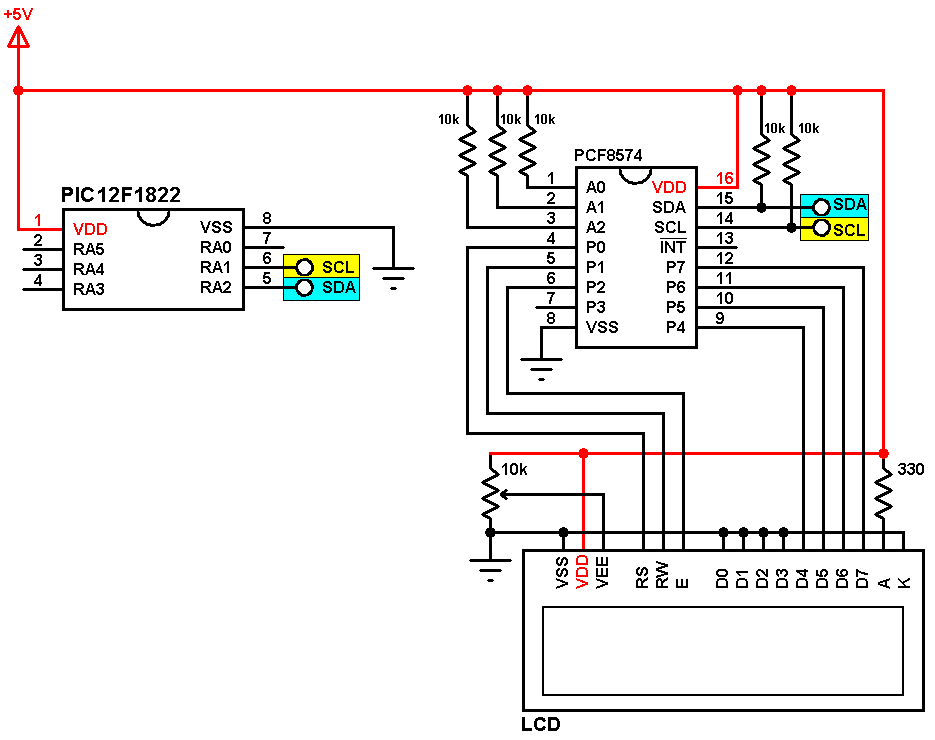
(All grounded terminals are connected together)
The PIC12F1822 microcontroller has one hardware I2C module with SDA on pin RA2 (#5) and SCL on pin RA1 (#6). SDA and SCL pins of the PIC12F1822 MCU are connected to SDA (#15) and SCL (#14) pins of the PCF8574 I/O expander respectively.
A2, A1 and A0 pins of the PCF8574 are connected to +5V (each one through 10k resistor) which means the I2C address of the PCF8574 (therefor the I2C LCD) is: 0 1 0 0 A2 A1 A0 0 = 0 1 0 0 1 1 1 0 = 0x4E. The 10k ohm resistors for A2, A1 and A0 are optional and each pin can be connected directly to +5V.
PCF8574A can be used instead of the PCF8574, the I2C address becomes: 0x7E.
In this project the PIC12F1822 microcontroller runs with its internal oscillator @ 8 MHz, MCLR pin is configured as an input pin.
Interfacing PIC12F1822 microcontroller with I2C LCD C code:
The following C code is for mikroC PRO for PIC compiler, it was tested with version 7.2.0.
The I2C LCD driver file is included with the line:
#include “I2C_LCD.c”
The hardware I2C module of the PIC12F1822 is initialized with a clock frequency of 100KHz (100000Hz):
I2C1_Init(100000);
The I2C LCD is initialized with an I2C address of 0x4E:
LCD_Begin(0x4E);
Full mikroC code:
Configuration words:
CONFIG1 = 0x3F84
CONFIG2 = 0x1613
1 2 3 4 5 6 7 8 9 10 11 12 13 14 15 16 17 18 19 20 21 22 23 24 25 26 27 28 29 30 31 32 33 34 35 36 37 38 39 40 41 42 | /* * Interfacing PIC12F1822 microcontroller with I2C LCD screen * C Code for mikroC PRO for PIC compiler * Internal oscillator used @ 8MHz * This is a free software with NO WARRANTY * http://simple-circuit.com/ */ // include I2C LCD driver source file #include "I2C_LCD.c" char i = 0, text[4]; void main() { OSCCON = 0x70; // set internal oscillator to 8MHz I2C1_Init(100000); // initialize I2C bus with clock frequency of 100kHz LCD_Begin(0x4E); // initialize LCD module with I2C address = 0x4E LCD_Goto(2, 1); // move cursor to column 1, row 1 LCD_Print("Hello, world!"); while(1) { // store 'i' into 'text' ( '0' for ASCII format ) text[0] = i / 100 + '0'; // store hundreds text[1] = (i / 10) % 10 + '0'; // store tens text[2] = i % 10 + '0'; // store ones LCD_Goto(7, 2); // move cursor to column 7, row 2 LCD_Print(text); // print 'text' i++; // increment i delay_ms(500); // wait 0.5 second } } // end of code. |
can you make a code for pic16f877a
una consulta se podrá utilizar esta misma librería con el pic 16f876a en xc8
This may help you:
http://simple-circuit.com/mplab-xc8-i2c-lcd-pic-microcontroller/