This post shows how to make a real time clock using PIC12F1822 microcontroller and DS3231 RTC chip (or DS1307 RTC) where time and date are displayed on 16×2 LCD. The DS3231 as well as the 16×2 LCD are connected to the same I2C bus with the PIC12F1822 microcontroller. The LCD is provided with PCF8574 I/O expander which makes it an I2C LCD. This project works also with DFRobot I2C LCD displays.
Last time I made an interfacing of PIC12F1822 and I2C LCD, project link is below:
Interfacing PIC12F1822 microcontroller with I2C LCD
In this project the DS3231 (DS1307) and the I2C LCD share the same I2C bus which means the SDA lines of the two devices are connected together and the SCL lines also, that minimizes number of pins used.
Time and date are displayed on the 16×2 LCD and they can be set with two push buttons connected to the PIC12F1822 microcontroller. With two pins for the I2C bus and two other pins for the push buttons, the microcontroller will use 4 pins (if internal oscillator is used).
Hardware Required:
The components required for this project are listed below.
- PIC12F1822 microcontroller
- DS3231 (or DS1307) board
- 16×2 LCD screen
- PCF8574 I/O expander (or PCF8574A) — PCF8574 datasheet
- 2 x pushbutton
- 5 x 10k ohm resistor
- 330 ohm resistor
- 10k ohm variable resistor or potentiometer
- 3V coin cell battery
- 5V source
- Breadboard
- Jumper wires

The Circuit:
Project circuit diagram is shown below.
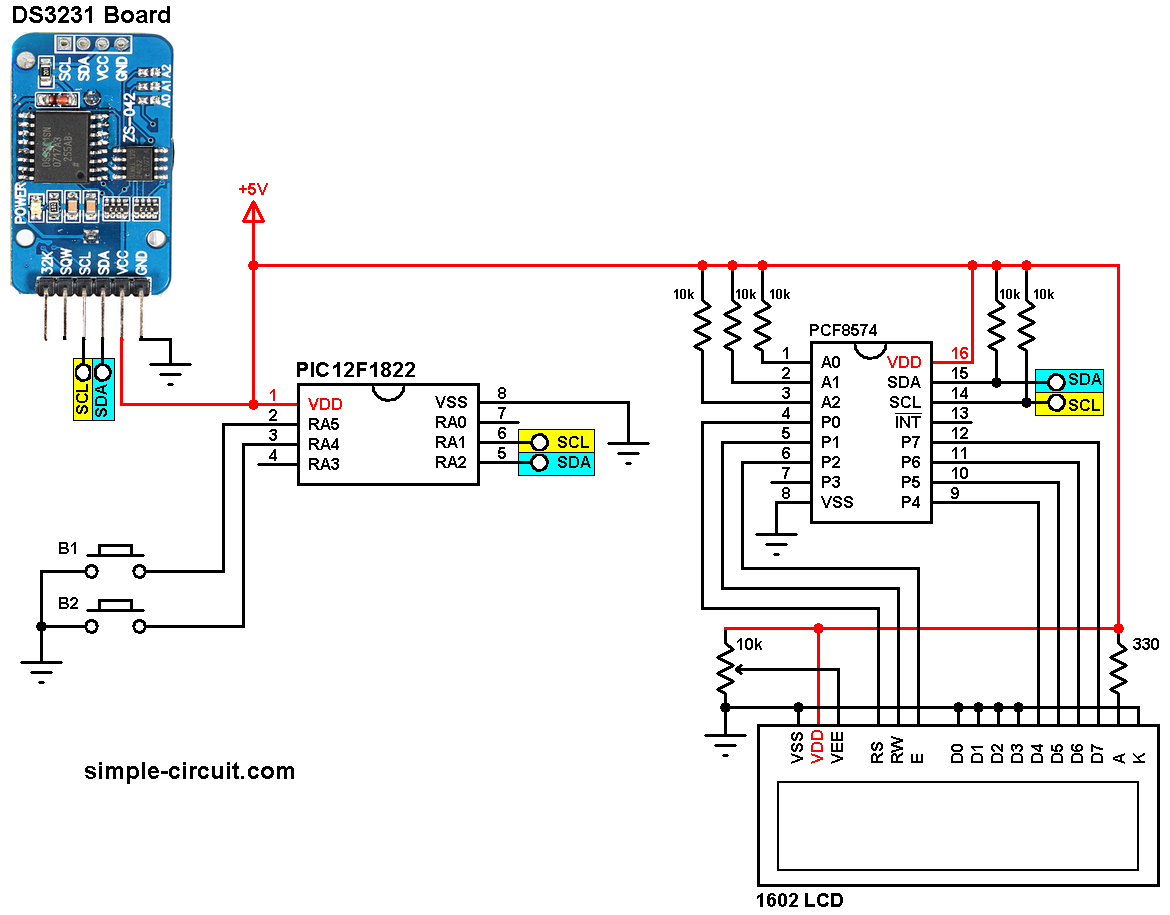
(All grounded terminals are connected together)
The PIC12F1822 microcontroller has one hardware I2C module with SDA on pin RA2 (#5) and SCL on pin RA1 (#6).
The I2C LCD and the DS3231 (or DS1307) board share the same I2C bus which means the SDA line of the I2C LCD (presented by PCF8574) and the DS3231 RTC chip are connected together with RA2 pin of the PIC12F1822 MCU, the SCL line of the I2C LCD and the SCL line of the DS3231 are connected together with RA1 pin of the PIC12F1822 MCU.
The two push buttons in the circuit are used to set time and date of the real time clock, button 1 (B1) is connected to RA5 pin (#2) and button 2 (B2) is connected to RA4 pin (#3) of the PIC12F1822 MCU.
PIC12F1822 internal oscillator is used (@8MHz) and MCLR pin (RA3) is configured as an input pin.
The Code:
The code below works with DS3231 and DS1307 without any modification. It was tested with CCS C compiler version 5.051.
To be able to compile the C code below, a driver for the I2C LCD is required, download link is in the following topic:
I2C LCD driver for CCS PIC C compiler
Or it can be downloaded from this link:
I2C LCD driver download
I2C LCD and DS3231 (DS1307) share the same I2C bus and the PIC12F1822 MCU communicates only with 1 device at a time depending on the address, the I2C LCD address is 0x4E and the DS3231 (the DS1307 also) address is 0xD0.
CCS C code:
1 2 3 4 5 6 7 8 9 10 11 12 13 14 15 16 17 18 19 20 21 22 23 24 25 26 27 28 29 30 31 32 33 34 35 36 37 38 39 40 41 42 43 44 45 46 47 48 49 50 51 52 53 54 55 56 57 58 59 60 61 62 63 64 65 66 67 68 69 70 71 72 73 74 75 76 77 78 79 80 81 82 83 84 85 86 87 88 89 90 91 92 93 94 95 96 97 98 99 100 101 102 103 104 105 106 107 108 109 110 111 112 113 114 115 116 117 118 119 120 121 122 123 124 125 126 127 128 129 130 131 132 133 134 135 136 137 138 139 140 141 142 143 144 145 146 147 148 149 150 151 152 153 154 155 156 157 158 159 160 161 162 163 164 165 166 167 168 169 170 171 172 173 174 175 176 177 178 | /* Real time clock with PIC12F1822, DS3231 and I2C LCD This code works also with DS1307 & DS3232 Two buttons B1 and B2 are used to set time and date C Code for CCS C compiler I2C LCD driver is required Internal oscillator used @ 8MHz */ #define button1 PIN_A5 // Button B1 is connected to RA5 pin #define button2 PIN_A4 // Button B2 is connected to RA4 pin #include <12F1822.h> #fuses NOMCLR INTRC_IO PLL_SW #use delay(clock=8000000) #use fast_io(A) #use I2C(master, I2C1, FAST = 100000, STREAM = I2C_LCD) // Include I2C_LCD driver source code #include <I2C_LCD.c> // Variables declaration int8 i, second, minute, hour, date, month, year; // Convert BCD to decimal function int8 bcd_to_decimal(number) { return((number >> 4) * 10 + (number & 0x0F)); } // Convert decimal to BCD function int8 decimal_to_bcd(number) { return(((number / 10) << 4) + (number % 10)); } // Display time and date function void ds3231_display() { // Convert data from BCD format to decimal format second = bcd_to_decimal(second); minute = bcd_to_decimal(minute); hour = bcd_to_decimal(hour); date = bcd_to_decimal(date); month = bcd_to_decimal(month); year = bcd_to_decimal(year); // End conversion LCD_Goto(13, 1); printf(LCD_Out,"%02u", second); // Display seconds LCD_Goto(10, 1); printf(LCD_Out,"%02u", minute); // Display minutes LCD_Goto(7, 1); printf(LCD_Out,"%02u", hour); // Display hours LCD_Goto(7, 2); printf(LCD_Out,"%02u", date); // Display date LCD_Goto(10, 2); printf(LCD_Out,"%02u", month); // Display month LCD_Goto(15, 2); printf(LCD_Out,"%02u", year); // Display year } // Make editing parameter blinks function void blink() { int8 j = 0; while(j < 10 && input(button1) && input(button2)) { j++; delay_ms(25); } } // Edit time and date function int8 edit(x, y, parameter) { delay_ms(50); while(!input(button1)); // Wait for button B1 release while(TRUE) { while(!input(button2)) { // If button B2 is pressed parameter++; if(i == 0 && parameter > 23) // If hours > 23 ==> hours = 0 parameter = 0; if(i == 1 && parameter > 59) // If minutes > 59 ==> minutes = 0 parameter = 0; if(i == 2 && parameter > 31) // If date > 31 ==> date = 1 parameter = 1; if(i == 3 && parameter > 12) // If month > 12 ==> month = 1 parameter = 1; if(i == 4 && parameter > 99) // If year > 99 ==> year = 0 parameter = 0; LCD_Goto(x, y); printf(LCD_Out,"%02u", parameter); // Display parameter delay_ms(200); // Wait 200ms } LCD_Goto(x, y); LCD_Out(" "); blink(); LCD_Goto(x, y); // Display two spaces printf(LCD_Out,"%02u", parameter); // Display parameter blink(); if(!input(button1)){ // If button B1 is pressed i++; // Increament 'i' for the next parameter return parameter; // Return parameter value and exit } } } void main() { setup_oscillator(OSC_8MHZ); // Set internal oscillator to 8MHz port_a_pullups(0x30); // Enable RA4 & RA5 internal pull-ups LCD_Begin(0x4E); // Initialize LCD module with address = 0x4E LCD_Goto(1, 1); LCD_Out("TIME: 00:00:00"); LCD_Goto(1, 2); LCD_Out("DATE: 00/00/2000"); while(TRUE) { if(!input(button1)) { // If button B1 is pressed i = 0; hour = edit(7, 1, hour); minute = edit(10, 1, minute); date = edit(7, 2, date); month = edit(10, 2, month); year = edit(15, 2, year); // Convert decimal to BCD minute = decimal_to_bcd(minute); hour = decimal_to_bcd(hour); date = decimal_to_bcd(date); month = decimal_to_bcd(month); year = decimal_to_bcd(year); // End conversion // Write data to DS3231 RTC i2c_start(I2C_LCD); // Start I2C i2c_write(I2C_LCD, 0xD0); // DS3231 address i2c_write(I2C_LCD, 0); // Send register address i2c_write(I2C_LCD, 0); // Reset sesonds and start oscillator i2c_write(I2C_LCD, minute); // Write minute value to DS3231 i2c_write(I2C_LCD, hour); // Write hour value to DS3231 i2c_write(I2C_LCD, 1); // Write day value (not used) i2c_write(I2C_LCD, date); // Write date value to DS3231 i2c_write(I2C_LCD, month); // Write month value to DS3231 i2c_write(I2C_LCD, year); // Write year value to DS3231 i2c_stop(I2C_LCD); // Stop I2C delay_ms(200); } // Read current time and date from DS3231 i2c_start(I2C_LCD); // Start I2C i2c_write(I2C_LCD, 0xD0); // DS3231 address i2c_write(I2C_LCD, 0); // Send register address i2c_start(I2C_LCD); // Restart I2C i2c_write(I2C_LCD, 0xD1); // Initialize data read second = i2c_read(I2C_LCD, 1); // Read seconds from register 0 minute = i2c_read(I2C_LCD, 1); // Read minuts from register 1 hour = i2c_read(I2C_LCD, 1); // Read hour from register 2 i2c_read(I2C_LCD, 1); // Read day from register 3 (not used) date = i2c_read(I2C_LCD, 1); // Read date from register 4 month = i2c_read(I2C_LCD, 1); // Read month from register 5 year = i2c_read(I2C_LCD, 0); // Read year from register 6 i2c_stop(I2C_LCD); // Stop I2C DS3231_display(); // Diaplay time & date delay_ms(50); } } // End of code. |
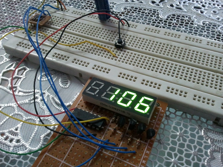
The following video shows a breadboard circuit of the project:
and the one below shows Proteus simulation where DS1307 RTC is used. Using DS3232 chip will give the same result:
Proteus simulation file download:
PIC12F1822 + DS1307 + I2C LCD
Hey,
Where can I find the I2C functions library? I can’t find it.
So I can’t use the i2c_start (and other) functions.
Project code is for CCS C compiler, not for MPLAB XC8 or mikroC!