This topic shows how to decode IR remote control uses extended NEC communication protocol.
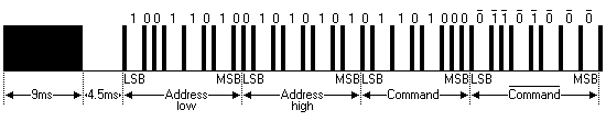
The complete extended NEC protocol message is started by 9ms burst followed by 4.5ms space which is then followed by the Address and Command. The address is 16-bit length and the command is transmitted twice (8 bits + 8 bits) where in the second time all bits are inverted and can be used for verification of the received message. The following drawing shows an extended NEC message example.
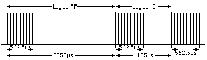
The NEC protocol uses pulse distance encoding of the bits. Each pulse is a 562.5µs long with carrier frequency of 38KHz. Logic bits are transmitted as follows:
Logic 0: 562.5µs pulse burst followed by a 562.5µs space, with a total transmit time of 1125µs (562.5 x 2).
Logic 1: a 562.5µs pulse burst followed by a 1687.5µs (562.5 x 3) space, with a total transmit time of 2250µs (562.5 x 4).
Extended NEC Protocol Decoder Using PIC12F1822:
Components List:
- PIC12F1822 microcontroller
- 1602 LCD
- 10K Variable Resistor
- 74HC595 Shift Register (74HC164, CD4094…..)
- IR Receiver
- 47µF Capacitor
- 10K Resistor
- +5V Power Supply
- Protoboard
- Jumper Wires
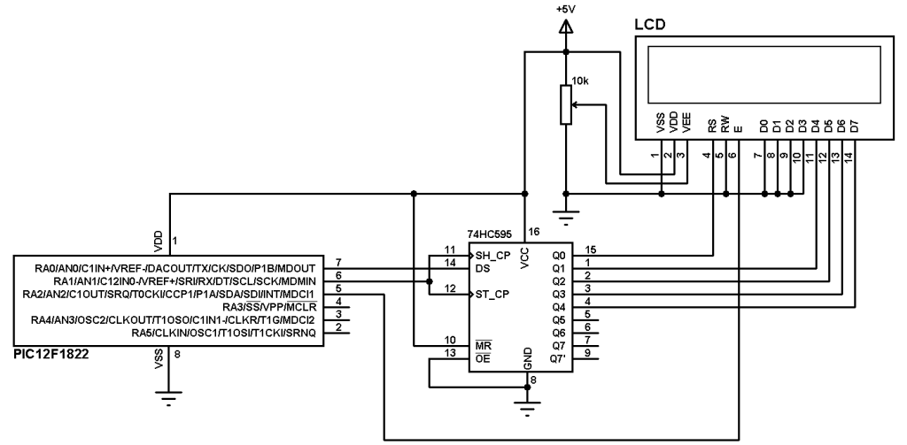
Extended NEC protocol decoder using PIC12F1822 circuit schematic is shown below where a 1602 LCD is used to display the NEC protocol parameters (address and command). To see how to interface this LCD with PIC12F1822 read the following topic:
Interfacing PIC12F1822 microcontroller with LCD display
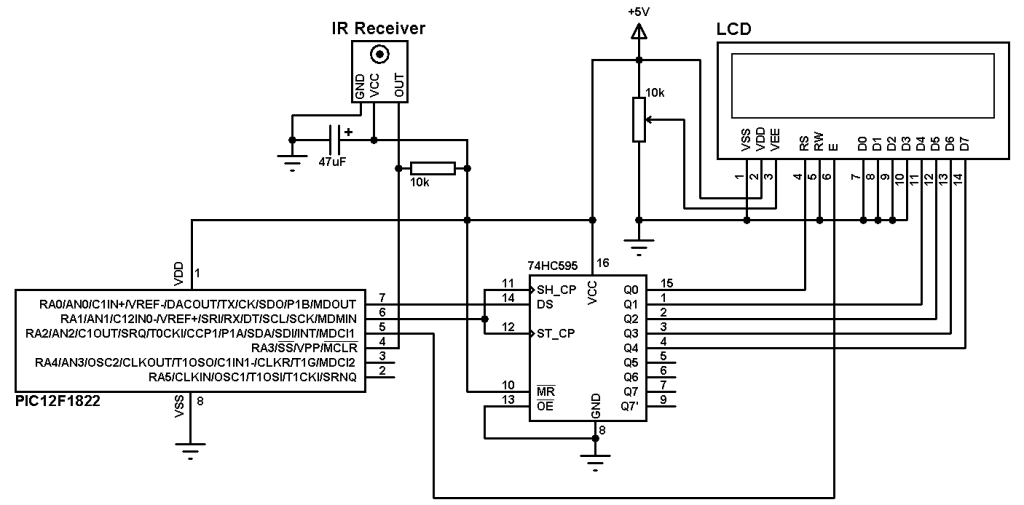
In this project PIC12F1822 microcontroller internal oscillator is used and MCLR pin is configured to work as a digital input.
By adding the shift register we can make a low coast 3-wire LCD.
A pull-up resistor (10KOhm) between VCC and the IR receiver output pin minimizes the noise on that pin.
To see how to use 74HC164 or CD4094 instead of 74HC595 read the topic at the link above.
Extended NEC Protocol Decoder C code:
PIC12F1822 microcontroller internal oscillator is set to 8MHz with PLL enabled which makes the microcontroller runs at 8 x 4 = 32MHz. The following line is used to deo that:
setup_oscillator(OSC_8MHZ | OSC_PLL_ON);
Timer1 is set to increment by 1 every 1us:
SETUP_TIMER_1(T1_INTERNAL | T1_DIV_BY_8);
Timer1 is used to measure pulses and spaces duration in us.
The extended NEC message code has a total of 32 bits which can be divided into 3 parts:
The first 16 bits are for address (address low and address high)
The next 8 bits for command and the last 8 bits for the inverted command.
Basically the microcontroller waits until the IR receiver receives an IR signal which makes its output change its state from high to low. This is done using the following line:
while(input(IR_Sensor));
Where IR_Sensor is the pin where the IR receiver output connected to.
After that a function named nec_remote_read() is called, this function checks if the received signal has NEC protocol form all the time and reads the message code bits.
if(nec_remote_read())
Timer1 is used to calculate pulses and space in microseconds. For example to check the 9ms burst the following lines are used:
SET_TIMER1(0);
while(!input(IR_Sensor) && (count < 9500))
count = GET_TIMER1();
if( (count > 9499) || (count < 8500))
return FALSE;
The variable count is used to store Timer1 value. An interval between 8500us and 9500us is used to check the 9ms burst (9000us).
The same thing is done for the 4.5ms space.
The complete CCS C code for the NEC decoder is as the one below, it was tested with version 5.051.
1 2 3 4 5 6 7 8 9 10 11 12 13 14 15 16 17 18 19 20 21 22 23 24 25 26 27 28 29 30 31 32 33 34 35 36 37 38 39 40 41 42 43 44 45 46 47 48 49 50 51 52 53 54 55 56 57 58 59 60 61 62 63 64 65 66 67 68 69 70 71 72 73 74 75 76 77 78 79 80 | // Extended NEC protocol IR remote control decoder using PIC12F1822 CCS C code // 3-Wire LCD driver must be added //LCD module connections #define LCD_DATA_PIN PIN_A0 #define LCD_CLOCK_PIN PIN_A1 #define LCD_EN_PIN PIN_A2 //End LCD module connections #include <12F1822.h> #fuses NOMCLR INTRC_IO PLL_SW #use delay(clock=32000000) #include <3WireLCD.c> #use fast_io(A) #define IR_Sensor PIN_A3 unsigned int32 ir_code; unsigned int16 address; unsigned int8 command, inv_command; short nec_remote_read(){ unsigned int16 count = 0; unsigned int8 i; // Check 9ms pulse (remote control sends logic high) SET_TIMER1(0); while(!input(IR_Sensor) && (count < 9500)) count = GET_TIMER1(); if( (count > 9499) || (count < 8500)) return FALSE; // Check 4.5ms space (remote control sends logic low) SET_TIMER1(0); count = 0; while((input(IR_Sensor)) && (count < 5000)) count = GET_TIMER1(); if( (count > 4999) || (count < 4000)) return FALSE; // Read message (32 bits) for(i = 0; i < 32; i++){ SET_TIMER1(0); count = 0; while(!input(IR_Sensor) && (count < 650)) count = GET_TIMER1(); if( (count > 649) || (count < 500)) return FALSE; count = 0; SET_TIMER1(0); while((input(IR_Sensor)) && (count < 1800)) count = GET_TIMER1(); if( (count > 1799) || (count < 400)) return FALSE; if( count > 1000) // If space width > 1ms bit_set(ir_code, (31 - i)); // Write 1 to bit (31 - i) else // If space width < 1ms bit_clear(ir_code, (31 - i)); // Write 0 to bit (31 - i) } return TRUE; } void main() { setup_oscillator(OSC_8MHZ | OSC_PLL_ON); // Set internal oscillator to 32MHz (8MHz and PLL) lcd_initialize(); // Initialize LCD module lcd_cmd(LCD_CLEAR); // LCD Clear SETUP_TIMER_1(T1_INTERNAL | T1_DIV_BY_8); lcd_goto(1, 1); // Go to column 1 line 1 printf(lcd_out, "Address:0x0000"); lcd_goto(1, 2); // Go to column 1 line 2 printf(lcd_out, "Com:0x00 In:0x00"); while(TRUE){ while(input(IR_Sensor)); // Wait until IR_Sensor pin falls if(nec_remote_read()){ address = ir_code >> 16; command = ir_code >> 8; inv_command = ir_code; lcd_goto(11, 1); // Go to column 11 line 1 printf(lcd_out,"%4LX",address); lcd_goto(7, 2); // Go to column 7 line 2 printf(lcd_out,"%2X",command); lcd_goto(15, 2); // Go to column 15 line 2 printf(lcd_out,"%2X",inv_command); delay_ms(200);} } } |
NEC Protocol decoder with PIC12F1822 video:
Reference:
http://www.sbprojects.com/