This topic shows an easy and effective way for decoding IR (Infra-Red) remote controls that use Philips RC-5 communication protocol, but first we’ve to understand how the RC5 protocol works.
This Wikipedia links has good infos about the RC5 protocol.
The RC-5 protocol was developed by Philips in the late 1980s as a semi-proprietary consumer IR (infrared) remote control communication protocol for consumer electronics.
The RC5 has 14 bits per 1 code transmission, the 14 bits can be divided into 4 parts:
The first 2 bits are start bits and they are always logic 1.
The third bit called toggle bit, it can be logic 1 or logic 0.
The next 5 bits are address bits, each device type has its address number for example TV address number is 0, CD player address = 20 …………
And the last 6 bits are command bits, each button has its command number.
For the same device for example TV all the remote control buttons has the same address but each button has its command.
The toggle bit changes whenever a button is pressed.
The RC5 protocol uses Manchester coding, logic 1 and logic 0 are coded as shown in the following drawing where toggle bit is 1, address = 0 and command is 2:

RC-5 Protocol state machine:
I used the state machine shown below for decoding the RC5 protocol. The RC5 state machine checks the length of pulses and spaces transmitted from the remote control to go from state to another.
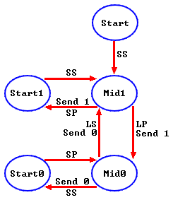
where:
SP : Short Pulse (About 889µs)
LP : Long Pulse (About 1778µs)
SS: Short Space (About 889µs)
LS : Long Space (About 1778µs)
Basically there are 4 states: Mid1, Mid0, Start1 and Start0.
RC-5 IR remote control decoder with PIC12F1822 circuit:

Components List:
- PIC12F1822 Microcontroller
- 1602 LCD
- 74HC595 Shift Register (74HC164, CD4094 ….)
- IR Receiver
- 47µF Capacitor
- 10K Resistor
- 10K Variable Resistor
- +5V Power Supply
- Protoboard
- Jumper Wires
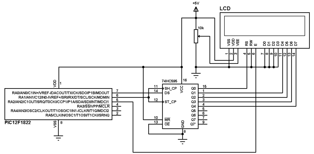
To interface 1602 LCD with PIC12F1822 microcontroller we need 74HC595 shift register as what was done in this post:
Interfacing PIC12F1822 microcontroller with LCD display
The IR receiver is used to receive the IR signals transmitted from the remote control and convert this signals to a digital data (logic 0 and logic 1). The microcontroller reads digital data from the IR receiver, this data is decoded and the results displayed on the 1602 LCD.
The idle state of the IR receiver output is logic 1 (+5V). When the IR receiver receives a pulse which comes from the remote control its output (IR receiver) gives logic 0 (0V).
PIC12F1822 internal oscillator is used and MCLR pin is configured as digital input.
RC-5 IR remote control decoder with PIC12F1822 CCS C code:
Timer1 is configured to increment by 1 every 1µs, it is used to measure pulses and spaces widths.
To measure pulses and spaces width in µs I used two functions and I called them respectively:
test_pulse() and test_space().
The previous two functions returns the following three values:
0 : If the width is out of range
1 : If the width is long (long pulse or long space)
2 : If the width is short (short pulse or short space)
If the IR receives an IR signal its output pin goes from logic 1 to logic 0 which causes the microcontroller to start reading the IR signal using the function: remote_read() and the state machine changes from start state to mid1 state. This function returns TRUE if the IR signal is an RC5 signal and returns FALSE if the IR signal is not RC5.
Both address and command numbers are displayed in hexadecimal format and the two start bits are not displayed because they are always 1s.
After receiving the IR code with successful this code which is stored in variable ir_code is split into three numbers: toggle bit (1 bit), address (5 bits) and command (6 bits).
The two start bit which are not displayed are represented by bits 12 and 13 of the variable ir_code (bit 0 is LSB).
Toggle bit : bit 11
Address : bits 6, 7, 8, 9 and 10
Command : bits 0, 1 , 2, 3 , 4 and 5.
Complete CCS C code, it was tested with version 5.051.
1 2 3 4 5 6 7 8 9 10 11 12 13 14 15 16 17 18 19 20 21 22 23 24 25 26 27 28 29 30 31 32 33 34 35 36 37 38 39 40 41 42 43 44 45 46 47 48 49 50 51 52 53 54 55 56 57 58 59 60 61 62 63 64 65 66 67 68 69 70 71 72 73 74 75 76 77 78 79 80 81 82 83 84 85 86 87 88 89 90 91 92 93 94 95 96 97 98 99 100 101 102 103 104 105 | // RC5 Protocol IR remote control decoder with PIC12F1822 CCS C code // 3-Wire LCD driver must be added //LCD module connections #define LCD_DATA_PIN PIN_A0 #define LCD_CLOCK_PIN PIN_A1 #define LCD_EN_PIN PIN_A2 //End LCD module connections #include <12F1822.h> #fuses NOMCLR INTRC_IO PLL_SW #use delay(clock = 32000000) #include <3WireLCD.c> #use fast_io(A) #define IR_Sensor PIN_A3 short toggle_bit; unsigned int8 address, command; unsigned int16 ir_code, count; int8 test_pulse(){ SET_TIMER1(0); while(!input(IR_Sensor) && (count < 2000)) count = GET_TIMER1(); if((count > 1999) || (count < 700)) return 0; if(count > 1200) return 1; else return 2; } int8 test_space(){ SET_TIMER1(0); while(input(IR_Sensor) && (count < 2000)) count = GET_TIMER1(); if((count > 1999) || (count < 700)) return 0; if(count > 1200) return 1; else return 2; } // Follow the RC5 state machine to understand short remote_read(){ int8 i = 0, check; mid1: check = test_pulse(); if(check == 0) return FALSE; bit_set(ir_code, 13 - i); i++; if(i > 13) return TRUE; if(check == 1) goto mid0; else goto start1; mid0: check = test_space(); if((check == 0) && (i != 13)) return FALSE; bit_clear(ir_code, 13 - i); i++; if(i > 13) return TRUE; if(check == 1) goto mid1; else goto start0; start1: check = test_space(); if(check != 2) return FALSE; goto mid1; start0: check = test_pulse(); if(check != 2) return FALSE; goto mid0; } void main() { setup_oscillator(OSC_8MHZ | OSC_PLL_ON); // Set internal oscillator to 32MHz (8MHz and PLL) setup_adc_ports(NO_ANALOGS); // Configure all pins as digital output_a(0); set_tris_a(0x08); // Configure RA3 pin as input lcd_initialize(); // Initialize LCD module lcd_cmd(LCD_CLEAR); // LCD Clear SETUP_TIMER_1(T1_INTERNAL | T1_DIV_BY_8); // Configure Timer 1 to increment every 1 us lcd_goto(1, 1); lcd_out("ADS:0x00 TGL: 0"); lcd_goto(1, 2); lcd_out("CMD:0x00"); while(TRUE){ count = 0; while(input(IR_Sensor)); if(remote_read()){ toggle_bit = bit_test(ir_code, 11); address = (ir_code >> 6) & 0x1F; command = ir_code & 0x3F; lcd_goto(16, 1); printf(lcd_out,"%1u",toggle_bit); lcd_goto(7, 1); printf(lcd_out,"%2LX",address); // Display address in hex format lcd_goto(7, 2); printf(lcd_out,"%2LX",command); // Display command in hex format } } } |
Project video: