This project is a simple interfacing of SSD1306 OLED display with PIC12F1822 microcontroller which has only 128 bytes of RAM. This project shows how to write texts and print numbers on the screen.
The SSD1306 OLED used in this example is configured to work in I2C (IIC) mode. So, make sure that your SSD1306 OLED display is configured to work in I2C mode, some displays need jumper placing or some soldering. — IIC or I2C: Inter-Integrated Circuit —
Related Projects:
Interfacing PIC16F877A with SSD1306 OLED display
Real time clock with PIC12F1822, SSD1306 OLED and DS3231 RTC
Hardware Required:
- PIC12F1822 microcontroller
- SSD1306 OLED display
- 5V source
- Breadboard
- Jumper wires
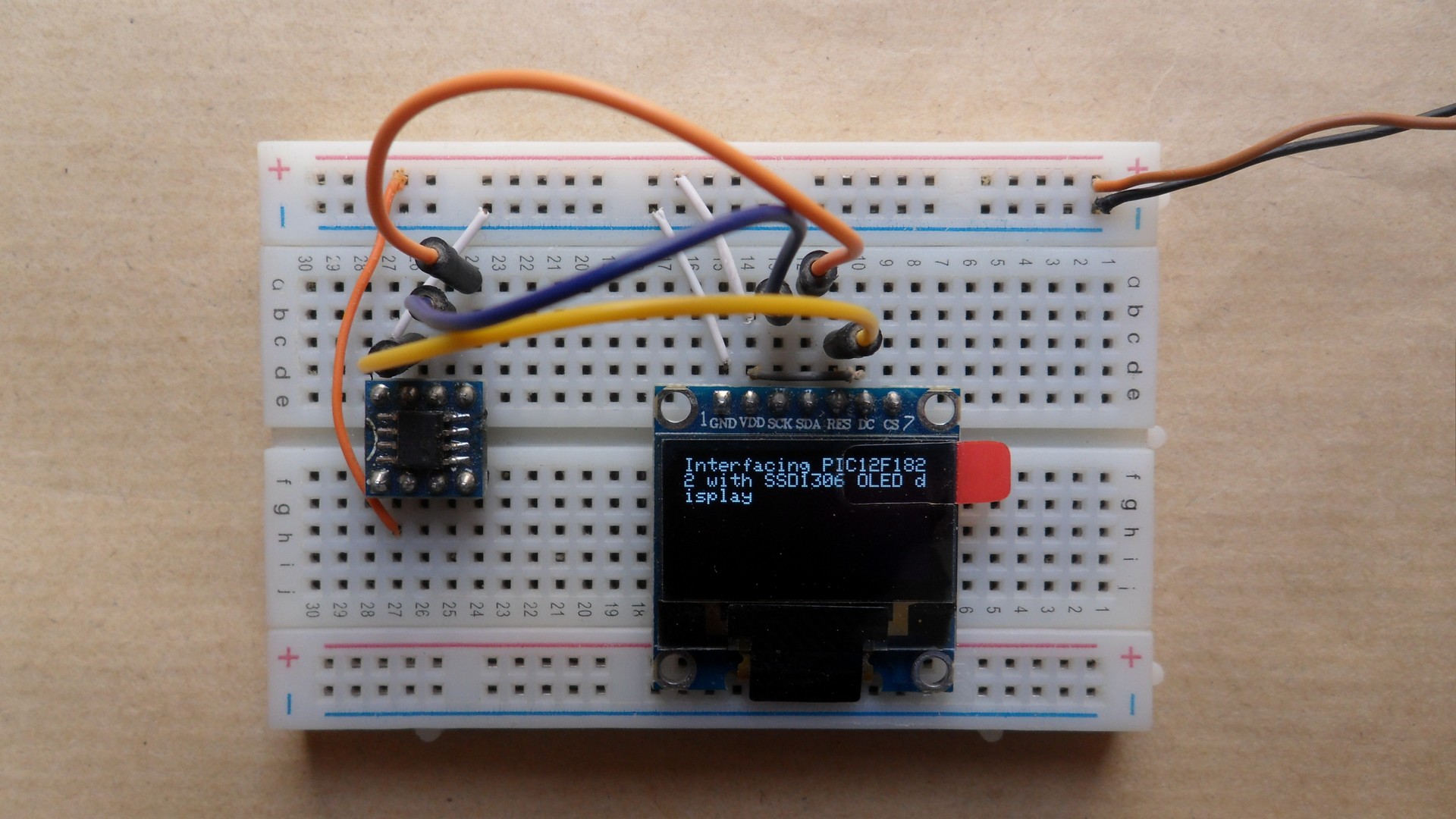
Interfacing PIC12F1822 with SSD1306 OLED circuit:
The following image shows project circuit schematic diagram.
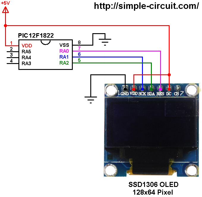
(All grounded terminal are connected together)
The PIC12F1822 microcontroller has one hardware I2C module with SDA on pin RA2 (#5) and SCL on pin RA1 (#6). The SDA pin of the MCU is connected to the SDA pin of the display and the SCL pin of the MCU is connected to the SCL (SCK) pin of the display.
The reset pin of the display is connected to pin RA0 (#7) of the microcontroller.
The SSD1306 OLED display DC pin is connected to VDD which means the I2C slave address of the display is 0x7A.
In this project the PIC12F1822 microcontroller uses with its internal oscillator @ 32 MHz, MCLR pin is configured as an input pin.
Interfacing PIC12F1822 with SSD1306 OLED C code:
The C code below is for CCS C compiler, it was tested with version 5.051 and version 5.079.
Version 5.051:
Used RAM: 31%
Used ROM: 66%
Version 5.079:
Used RAM: 27%
Used ROM: 66%
To be able to compile the C code below with no error, a driver for the SSD1306 OLED display is required, its name is SSD1306.C, download link is below:
SSD1306 OLED display driver
after the download, add the driver file to project folder or CCS C compiler drivers folder.
For more details about this driver see the following post:
Interfacing PIC16F877A with SSD1306 OLED display
CCS C code:
1 2 3 4 5 6 7 8 9 10 11 12 13 14 15 16 17 18 19 20 21 22 23 24 25 26 27 28 29 30 31 32 33 34 35 36 37 38 39 40 41 42 43 44 45 46 47 48 49 50 51 52 53 54 55 56 57 58 59 60 61 62 63 64 65 66 67 68 69 70 71 72 73 74 75 76 77 | /************************************************************************************** Interfacing PIC12F1822 with SSD1306 OLED display (128x64 Pixel) C Code for CCS C compiler Internal oscillator used @ 32MHz This is a free software with NO WARRANTY. http://simple-circuit.com/ ***************************************************************************************/ // SSD1306 OLED reset pin definition (if required) #define SSD1306_RST PIN_A0 #include <12F1822.h> #fuses NOMCLR INTRC_IO PLL_SW #use delay(clock = 32000000) #use fast_io(A) #use I2C(MASTER, I2C1, FAST = 400000, stream = SSD1306_STREAM) // Initialize I2C // Include SSD1306 OLED driver source code #include <SSD1306.c> int8 i = 0; // main function void main() { setup_oscillator(OSC_8MHZ | OSC_PLL_ON); // set internal oscillator to 32MHz (8MHz + PLL) delay_ms(500); // Initialize the SSD1306 OLED with an I2C addr = 0x7A (default address) SSD1306_Init(SSD1306_SWITCHCAPVCC, SSD1306_I2C_ADDRESS); // clear the display SSD1306_ClearDisplay(); SSD1306_GotoXY(1, 1); SSD1306_PutC("Interfacing PIC12F1822 with SSD1306 OLED display"); delay_ms(5000); SSD1306_ClearDisplay(); SSD1306_GotoXY(6, 2); SSD1306_PutC("Hello world!"); delay_ms(2000); SSD1306_StartScrollRight(1, 1); delay_ms(3000); SSD1306_StopScroll(); SSD1306_StartScrollLeft(1, 1); delay_ms(3000); SSD1306_StopScroll(); SSD1306_StartScrollDiagRight(1, 1); delay_ms(3000); SSD1306_StopScroll(); SSD1306_StartScrollDiagLeft(1, 1); delay_ms(3000); SSD1306_StopScroll(); delay_ms(3000); SSD1306_ClearDisplay(); SSD1306_GotoXY(6, 2); SSD1306_PutC("Hello world!"); delay_ms(2000); while(TRUE) { SSD1306_GotoXY(10, 5); printf(SSD1306_PutC, "%03u", i++); delay_ms(500); } } // End of code. |
Interfacing PIC12F1822 with SSD1306 OLED simulation:
The simulation of this project with Proteus should give a result similar to what shown in the following video where PIC16F877A microcontroller is used. Simulation file download link is below, use Proteus version 8.6 or higher to open it!
PIC12F1822 MCU + SSD1306 OLED
Thanks for the nice project.
the oled display module is said to work with 3.3 in many websites.
are you sure it is ok to sıpply it with 5volts?
Yes its controller (SSD1306) works with 3.3V only, but many modules (as the one shown in the circuit diagram) come with voltage regulator that supplies the display controller with 3.3V from 5V supply input. These modules also may contain voltage level converter for the lines between the MCU and the display controller.
For the I2C mode, the MCU sends a logic high by making its pin floating so a pull up resistor rises the line. The SSD1306 display module shown in the circuit diagram has 2 pull-up resistors for SDA and SCL lines, they’re connected to 3.3V.
So, before you connect your SSD1306 OLED display to a 5V microcontroller make sure there’s a voltage regulator placed in the board!