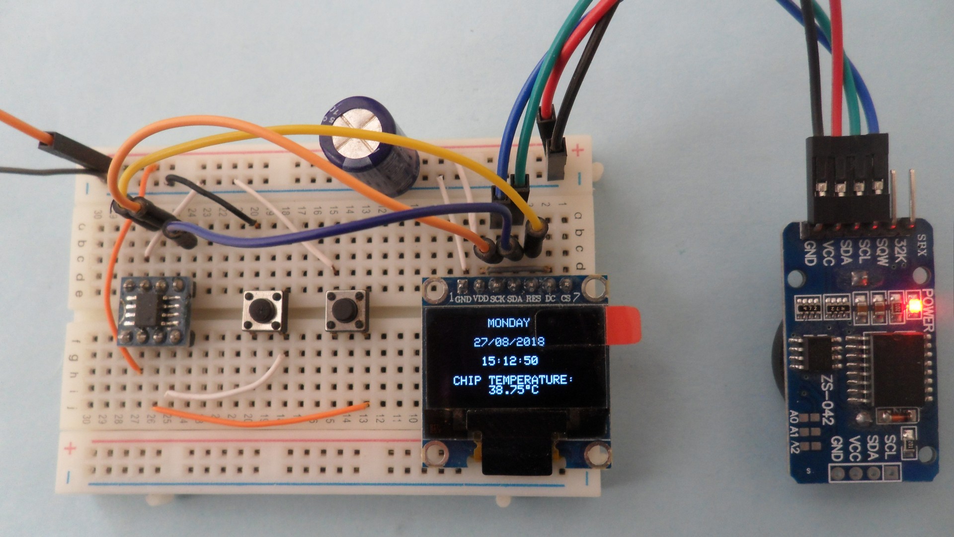
This post shows how to build a real time clock/calendar with temperature monitor using PIC12F1822 microcontroller, DS3231 RTCC and SSD1306 OLED display. Time and date are set with two push buttons and they are displayed on the SSD1306 OLED screen (128×64 Pixel).
The DS3231 has a buit-in temperature sensor which means we can use it for measuring the chip temperature.
The DS3231 is more accurate than the DS1307 due to its built-in temperature sensor. It also (the DS3231) keeps the time running if the main power source is down (with the help of a coin cell battery). It also uses I2C interface to communicate with the master device which is in this project PIC12F1822 microcontroller. This means the DS3231 and the SSD1306 OLED screen share the same I2C bus. Even they share the same bus but at any time the microcontroller ‘speaks’ with 1 device only depending on the address sent. The DS3231 RTC address is 0xD0 (the same as the DS1307 address) and the SSD1306 address is 0x7A.
In the circuit there are two push buttons for setting time and date of the real time clock.
Related Projects:
The following topics may contain some useful information about the current project.
Interfacing PIC12F1822 with SSD1306 OLED
Interfacing PIC12F1822 with DS3231/DS1307 and I2C LCD
PIC12F1822 + DS3231 + Remote Control with CCS C compiler
The SSD1306 OLED used in this project is configured to work in I2C mode, some SSD1306 OLED boards may require a small hardware modifications (to select between SPI mode or I2C mode) such as soldering, placing jumpers …
Hardware Required:
- PIC12F1822 microcontroller
- SSD1306 OLED display (128×64 Pixel)
- DS3231 board — DS3231 RTC datasheet
- 2 x push button
- 3V coin cell battery
- 5V power source
- Breadboard
- Jumper wires
Real time clock with PIC12F1822, SSD1306 OLED and DS3231 circuit:
The following image shows project circuit schematic diagram.
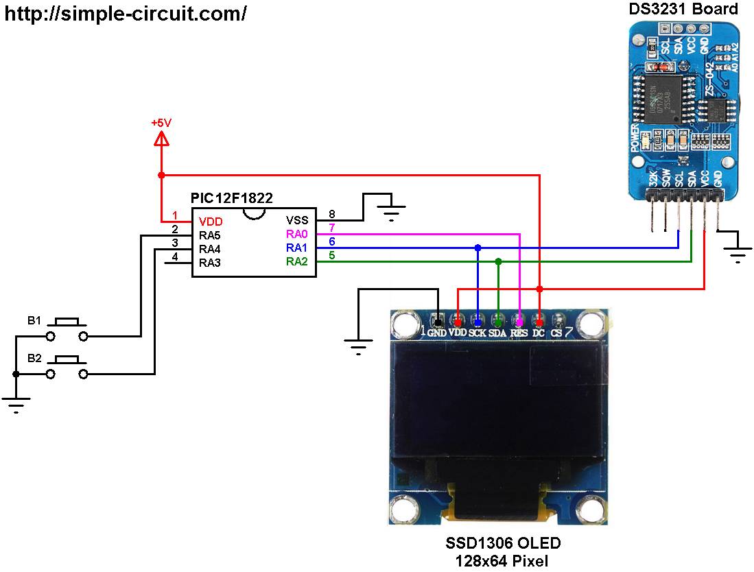
(All grounded terminals are connected together)
The two push buttons B1 and B2 are for setting time and date. Button B1 is connected to pin RA5 (#2) and B2 is connected to pin RA4 (#3). Internal pull-ups for the two input pins are enabled in the code.
PIC12F1822 microcontroller, DS3231 board and SSD1306 display board are supplied with 5V source between their VDD (or VCC) pin and GND pin.
In this project the PIC12F1822 microcontroller uses with its internal oscillator @ 32 MHz, MCLR pin is configured as an input pin.
Real time clock with PIC12F1822, SSD1306 OLED and DS3231 C code:
The C code below is for CCS C compiler, it was tested with version 5.051 and version 5.079.
Version 5.051:
Used RAM: 44%
Used ROM: 98%
Version 5.079:
Used RAM: 41%
Used ROM: 98%
To be able to compile the C code below with no error, a driver for the SSD1306 OLED display is required, it’s name is SSD1306.C, its download link is below:
SSD1306 OLED display driver
after the download, add the driver file to the project folder or CCS C compiler drivers folder.
The DS3231 RTC and the SSD1306 OLED display share the same I2C bus, DS3231 I2C address is 0xD0 and SSD1306 display I2C address is 0x7A.
CCS C code:
1 2 3 4 5 6 7 8 9 10 11 12 13 14 15 16 17 18 19 20 21 22 23 24 25 26 27 28 29 30 31 32 33 34 35 36 37 38 39 40 41 42 43 44 45 46 47 48 49 50 51 52 53 54 55 56 57 58 59 60 61 62 63 64 65 66 67 68 69 70 71 72 73 74 75 76 77 78 79 80 81 82 83 84 85 86 87 88 89 90 91 92 93 94 95 96 97 98 99 100 101 102 103 104 105 106 107 108 109 110 111 112 113 114 115 116 117 118 119 120 121 122 123 124 125 126 127 128 129 130 131 132 133 134 135 136 137 138 139 140 141 142 143 144 145 146 147 148 149 150 151 152 153 154 155 156 157 158 159 160 161 162 163 164 165 166 167 168 169 170 171 172 173 174 175 176 177 178 179 180 181 182 183 184 185 186 187 188 189 190 191 192 193 194 195 196 197 198 199 200 201 202 203 204 205 206 207 208 209 210 211 212 213 214 215 216 217 218 219 220 221 222 223 224 225 226 227 228 229 230 231 232 233 234 235 236 237 238 239 240 241 242 243 244 245 246 247 248 249 250 251 252 253 254 255 256 257 258 259 260 261 262 263 264 265 266 267 268 269 270 271 272 273 274 275 276 277 278 279 280 281 282 283 284 285 286 287 288 289 290 291 | /************************************************************************************** Real time clock/calendar with chip temperature monitor using PIC12F1822 microcontroller, SSD1306 OLED display (128x64 Pixel) and DS3231 RTC chip. C Code for CCS C compiler Internal oscillator used @ 32MHz This code works also with DS3232 Two buttons B1 and B2 for setting time and date This is a free software with NO WARRANTY. http://simple-circuit.com/ ***************************************************************************************/ // SSD1306 OLED reset pin definition (if required) #define SSD1306_RST PIN_A0 #define button1 PIN_A5 // button B1 is connected to RA5 pin #define button2 PIN_A4 // button B2 is connected to RA4 pin #include <12F1822.h> #fuses NOMCLR INTRC_IO PLL_SW #use delay(clock = 32000000) #use fast_io(A) #use I2C(MASTER, I2C1, FAST = 400000, stream = SSD1306_STREAM) // Initialize I2C // Include SSD1306 OLED driver source code #include <SSD1306.c> // Variables declaration signed int8 temperature_msb; int8 i, second, minute, hour, w_day, day, month, year, temperature_lsb; char degree[] = {0, 7, 5, 7, 0}; // degree symbol custom char int1 debounce (int8 button, int1 s) { int8 count = 0; for(int8 i = 0; i < 5; i++) { if (input(button) == s) count++; delay_ms(10); } if(count > 2) return 1; else return 0; } // convert BCD to decimal function int8 bcd_to_decimal(number) { return((number >> 4) * 10 + (number & 0x0F)); } // convert decimal to BCD function int8 decimal_to_bcd(number) { return(((number / 10) << 4) + (number % 10)); } // function for display day of the week void display_day() { SSD1306_GotoXY(7, 1); switch(w_day) { case 1: SSD1306_PutC(" SUNDAY "); break; case 2: SSD1306_PutC(" MONDAY "); break; case 3: SSD1306_PutC(" TUESDAY "); break; case 4: SSD1306_PutC("WEDNESDAY"); break; case 5: SSD1306_PutC("THURSDAY "); break; case 6: SSD1306_PutC(" FRIDAY "); break; default: SSD1306_PutC("SATURDAY "); } } void DS1307_display() { // convert data from BCD format to decimal format second = bcd_to_decimal(second); minute = bcd_to_decimal(minute); hour = bcd_to_decimal(hour); day = bcd_to_decimal(day); month = bcd_to_decimal(month); year = bcd_to_decimal(year); // end conversion // print time SSD1306_GotoXY(13, 5); printf(SSD1306_PutC, "%02u", second); // print seconds SSD1306_GotoXY(10, 5); printf(SSD1306_PutC, "%02u:", minute); // print minutes SSD1306_GotoXY(7, 5); printf(SSD1306_PutC, "%02u:", hour); // print hours // print date SSD1306_GotoXY(6, 3); printf(SSD1306_PutC, "%02u/", day); // print date SSD1306_GotoXY(9, 3); printf(SSD1306_PutC, "%02u/20", month); // print month SSD1306_GotoXY(14, 3); printf(SSD1306_PutC, "%02u", year); // print year // print temperature SSD1306_GotoXY(7, 8); if(temperature_msb < 0) { temperature_msb = abs(temperature_msb); SSD1306_PutC('-'); } else SSD1306_PutC(' '); printf(SSD1306_PutC, "%02u.", temperature_msb); switch (temperature_lsb) { case 0x00: SSD1306_PutC("00"); break; case 0x40: SSD1306_PutC("25"); break; case 0x80: SSD1306_PutC("50"); break; case 0xC0: SSD1306_PutC("75"); break; } SSD1306_PutCustomC(degree); // degree symbol ( ° ) SSD1306_PutC('C'); } void blink_parameter() { int8 j = 0; while(j < 10 && input(button1) && input(button2)) { j++; delay_ms(25); } } int8 edit(int8 x_pos, int8 y_pos, int8 parameter) { while(debounce(button1, 0)); // wait for button B1 release while(true){ while(!input(button2)) // if button B2 is pressed { parameter++; if(i == 0 && parameter > 31) // if date > 31 ==> date = 1 parameter = 1; if(i == 1 && parameter > 12) // if month > 12 ==> month = 1 parameter = 1; if(i == 2 && parameter > 99) // if year > 99 ==> year = 0 parameter = 0; if(i == 3 && parameter > 23) // if hours > 23 ==> hours = 0 parameter = 0; if(i == 4 && parameter > 59) // if minutes > 59 ==> minutes = 0 parameter = 0; SSD1306_GotoXY(x_pos, y_pos); printf(SSD1306_PutC, "%02u", parameter); delay_ms(200); // wait 200ms } SSD1306_GotoXY(x_pos, y_pos); SSD1306_PutC(" "); blink_parameter(); SSD1306_GotoXY(x_pos, y_pos); printf(SSD1306_PutC, "%02u", parameter); blink_parameter(); if(!input(button1)) // if button B1 is pressed if(debounce(button1, 0)) { i++; // increament 'i' for the next parameter return parameter; // return parameter value and exit } } } // main function void main() { setup_oscillator(OSC_8MHZ | OSC_PLL_ON); // set internal oscillator to 32MHz (8MHz + PLL) port_a_pullups(0x30); // enable RA4 & RA5 internal pull-ups delay_ms(1000); // initialize the SSD1306 OLED with an I2C addr = 0x7A (default address) SSD1306_Init(SSD1306_SWITCHCAPVCC, SSD1306_I2C_ADDRESS); // clear the whole display SSD1306_ClearDisplay(); SSD1306_GotoXY(3, 7); SSD1306_PutC("CHIP TEMPERATURE:"); while (TRUE) { if(!input(button1)) // if button B1 is pressed if(debounce(button1, 0)) { i = 0; while(debounce(button1, 0)) ; // wait for button B1 to be released while(TRUE) { while(!input(button2)) // while button B2 pressed { w_day++; // increment w_day if(w_day > 7) w_day = 1; display_day(); // call display_day function delay_ms(200); // wait 200 ms } SSD1306_GotoXY(7, 1); SSD1306_PutC(" "); blink_parameter(); // call blink_parameter function display_day(); // call display_day function blink_parameter(); // call blink_parameter function if(!input(button1)) // if button B1 is pressed if(debounce(button1, 0)) break; } day = edit(6, 3, day); // edit date month = edit(9, 3, month); // edit month year = edit(14, 3, year); // edit year hour = edit(7, 5, hour); // edit hours minute = edit(10, 5, minute); // edit minutes while(debounce(button1, 0)); // wait for button B1 to be released // convert decimal to BCD minute = decimal_to_bcd(minute); hour = decimal_to_bcd(hour); day = decimal_to_bcd(day); month = decimal_to_bcd(month); year = decimal_to_bcd(year); // end conversion // write data to DS3231 RTC i2c_start(SSD1306_STREAM); // start I2C i2c_write(SSD1306_STREAM, 0xD0); // DS3231 address i2c_write(SSD1306_STREAM, 0); // send register address i2c_write(SSD1306_STREAM, 0); // reset sesonds and start oscillator i2c_write(SSD1306_STREAM, minute); // write minute value to DS3231 i2c_write(SSD1306_STREAM, hour); // write hour value to DS3231 i2c_write(SSD1306_STREAM, w_day); // write day of week value to DS3231 i2c_write(SSD1306_STREAM, day); // write day value to DS3231 i2c_write(SSD1306_STREAM, month); // write month value to DS3231 i2c_write(SSD1306_STREAM, year); // write year value to DS3231 i2c_stop(SSD1306_STREAM); // stop I2C delay_ms(200); // wait 200ms } // read current time and date i2c_start(SSD1306_STREAM); // start I2C i2c_write(SSD1306_STREAM, 0xD0); // DS3231 address i2c_write(SSD1306_STREAM, 0); // send register address i2c_start(SSD1306_STREAM); // restart I2C i2c_write(SSD1306_STREAM, 0xD1); // initialize data read second = i2c_read(SSD1306_STREAM, 1); // read seconds from register 0 minute = i2c_read(SSD1306_STREAM, 1); // read minuts from register 1 hour = i2c_read(SSD1306_STREAM, 1); // read hour from register 2 w_day = i2c_read(SSD1306_STREAM, 1); // read day of week from register 3 day = i2c_read(SSD1306_STREAM, 1); // read day from register 4 month = i2c_read(SSD1306_STREAM, 1); // read month from register 5 year = i2c_read(SSD1306_STREAM, 0); // read year from register 6 i2c_stop(SSD1306_STREAM); // stop I2C // Read temperature i2c_start(SSD1306_STREAM); // start I2C i2c_write(SSD1306_STREAM, 0xD0); // DS3231 address i2c_write(SSD1306_STREAM, 0x11); // send register address (temperature MSB register) i2c_start(SSD1306_STREAM); // restart I2C i2c_write(SSD1306_STREAM, 0xD1); // initialize data read temperature_msb = i2c_read(SSD1306_STREAM, 1); // read temperature MSB temperature_lsb = i2c_read(SSD1306_STREAM, 0); // read temperature LSB i2c_stop(SSD1306_STREAM); // stop I2C display_day(); // display day of the week DS1307_display(); // diaplay time & Date delay_ms(50); // wait 50ms } } // End of code. |
The hardware circuit of this project should be the same as what shown in the following video where PIC16F877A MCU is used: