DC motor speed can be easily controlled if the microcontroller has CCP module to generate PWM (Pulse Width Modulation) signal, the speed is controlled when the PWM signal duty cycle is varied and if the duty cycle is changed the power delivered to the motor will be changed also. The microcontroller PIC16F84A is a very old chip but it is good for beginners to start PIC programming and electronics, it doesn’t have CCP module and it has only 1 timer which is Timer0 module, this timer is an 8-bit timer. Using this timer we are going to see how to make a software PWM in order to control the DC motor.
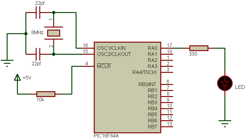
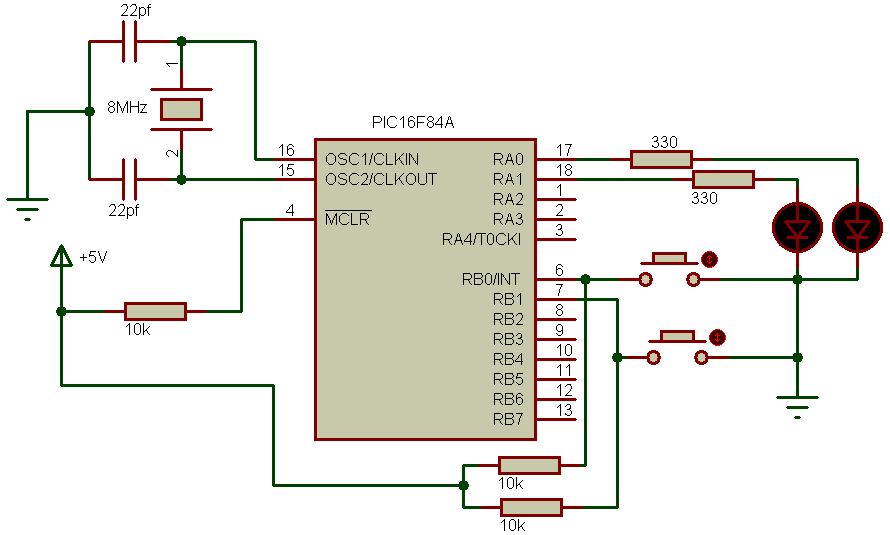
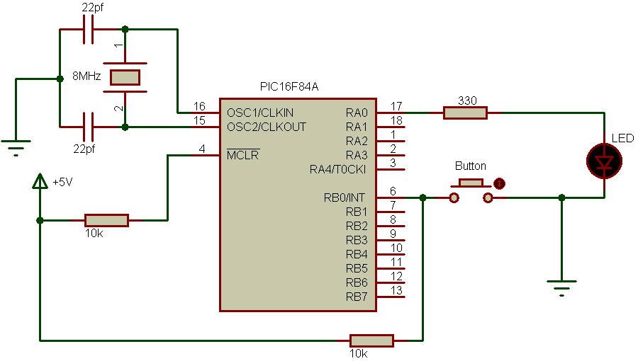
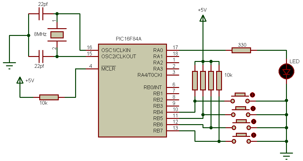
DC motor speed control using PIC16F84A circuit schematic:

The nominal voltage of the DC motor is 12V. The PIC16F84A microcontroller must be supplied with 5V between pins VDD and VSS.
In the circuit there are two buttons to increase and decrease the speed of the motor, these buttons are connected to RB0 and RB1 respectively.
There is an LED connected to RB2 used to indicate that the motor is at full speed. The crystal frequency is 8MHz and the transistor is N-type mosfet.
The following CCS C command line is used to generate a software PWM frequency using Timer0 with 500Hz frequency on RA0 pin:
#use pwm(output = pin_a0, timer = 0, frequency= 500Hz, duty = 0)
And the following command is used to to set the duty cycle:
pwm_set_duty_percent( duty ); // In tenths %
The complete CCS C code is as the following below:
1 2 3 4 5 6 7 8 9 10 11 12 13 14 15 16 17 18 19 20 21 22 23 24 25 26 27 28 29 30 | // DC motor speed control using PIC16F84A CCS C code #include <16F84A.h> #fuses HS,NOWDT,PUT,NOPROTECT #use delay(clock = 8000000) #use fast_io(B) #use pwm(output = pin_a0, timer = 0, frequency= 500Hz, duty = 0) unsigned int8 i; void main() { port_b_pullups(TRUE); // Enable PORTB pull-ups output_b(0); // PORTB initial state set_tris_b(3); // Configure RB0 & RB1 as inputs while(TRUE) { if(input(PIN_B0) == 0){ // If RB0 button pressed i++; // Increment i by 1 (i = i + 1) if(i > 100){ i = 100; output_high(PIN_B2);} // Turn RB2 LED ON pwm_set_duty_percent(i * 10UL); // Duty cycle change in tenths % delay_ms(100); } // Wait 100ms if(input(PIN_B1) == 0){ // If RB1 button pressed output_low(PIN_B2); // Turn RB2 LED OFF i--; // Decrement i by 1 (i = i - 1) if(i < 1) i = 1; pwm_set_duty_percent(i * 10UL); // Duty cycle change in tenths % delay_ms(100); } // Wait 100ms } } |
DC motor speed control using PIC16F84A video:
The following video shows the project using a hardware circuit.
PIC16F84A code hix
Pic16f84a hix file
THANKS SIR