The microcontroller PIC16F877A has two CCP modules CCP1 and CCP2, these modules could be used to give us two PWM signals. In this topic we are going to see how to use the two modules i order to control a DC motor speed and direction.
We can control the speed of DC motor using PWM technique as shown in the following topic:
DC Motor speed control with PIC16F877A and CCS PIC C compiler
And the direction of the DC motor can be controlled using H-Bridge circuit which allows us to reverse terminals polarity of the motor.
Related topics:
PIC16F877A ADC example with CCS PIC C compiler
PIC16F877A PWM example with CCS PIC C compiler
DC motor control with PIC16F877A circuit:
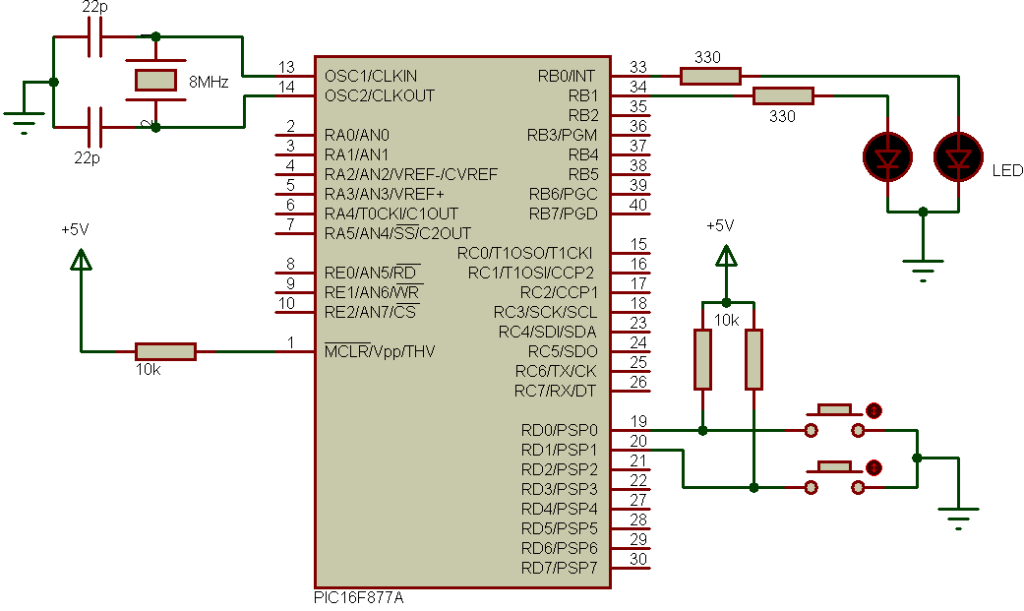
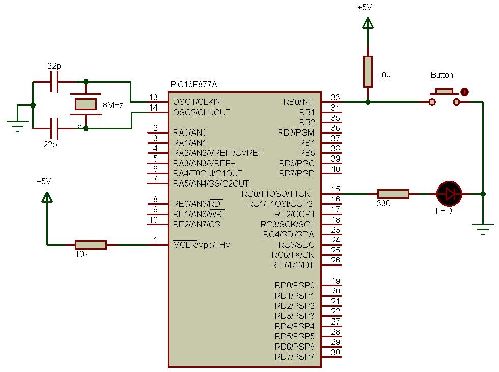
The following circuit schematic shows the full circuit of the project.

PORTB internal weak pull-ups are enabled in the software and therefore there is no need to add a pull-up resistor to pins RB0, RB1 and RB2.
There are 3 push buttons in the circuit 2 of them to choose rotation direction and the other one stops the motor. The two LEDs indicate rotation direction, if Direction 1 button is pressed the motor moves in the first direction and LED 1 on and the same thing for Direction 2 button and LED 2. The motor speed is controlled from potentiometer connected to RA0 (analog channel 0). The microcontroller PIC16F877A reads analog data from channel 0 and use the digital value to set the PWM duty cycle. If direction 1 button is pressed the microcontroller starts PWM1 (RC2 pin) and stops PWM2 (RC1 pin) and if direction 2 button is pressed the microcontroller stops PWM1 (RC2 pin) and starts PWM2 (RC1 pin), when the stop button is pressed the microcontroller stops PWM1 and PWM2 signals and the motor will stop.
The PWM (PWM1 & 2) frequency is 500Hz.
The basic elements of the H-bridge are the four MOSFETs (2 N-type and 2 P-type).
The PIC16F877A microcontroller needs to be supplied with 5V between oins VDD and VSS.
DC motor control with PIC16F877A CCS PIC C code:
PIC16F877A Timer2 is configured to generate a PWM signal with a frequency of 500Hz and the microcontroller runs with 8MHz crystal oscillator.
The microcontroller PIC16F877A reads RA0 analog value and stores the digital value on variable (i), this variable is used to set duty cycle of the active PWM (PWM1 or PWM2).
1 2 3 4 5 6 7 8 9 10 11 12 13 14 15 16 17 18 19 20 21 22 23 24 25 26 27 28 29 30 31 32 33 34 35 36 37 38 39 40 41 42 43 44 45 46 47 48 49 50 51 52 53 54 55 | // DC motor control using PIC16F877A CCS C code #include <16F877A.h> #fuses HS,NOWDT,NOPROTECT,NOLVP #device ADC = 10 #use delay(clock = 8000000) #use fast_io(B) #use fast_io(C) unsigned int16 i ; void main(){ port_b_pullups(TRUE); // Enable PORTB pull-ups output_b(0); // PORTB initial state set_tris_b(7); // Configure RB0, RB1 & RB2 as inputs output_c(0); // PORTC initial state set_tris_c(0); // Configure PORTC pins as outputs setup_adc(ADC_CLOCK_DIV_32); // Set ADC conversion time to 32Tosc setup_adc_ports(AN0); // Configure AN0 as analog set_adc_channel(0); // Select channel AN0 setup_timer_2(T2_DIV_BY_16, 250, 1); // Set PWM frequency to 500Hz delay_ms(100); // Wait 100ms while(TRUE){ i = read_adc(); // Read from AN0 and store in i if(input(PIN_B3) == 1) // If direction 1 is selected set_pwm1_duty(i); // Set pwm1 duty cycle if(input(PIN_B4) == 1) // If direction 2 is selected set_pwm2_duty(i); // Set pwm2 duty cycle delay_ms(10); // Wait 10ms if(input(PIN_B0) == 0){ // If RB0 button pressed if(input(PIN_B3) == 0){ // If direction 1 not already selected output_b(0); // Both LEDs OFF setup_ccp1(CCP_OFF); // CCP1 OFF setup_ccp2(CCP_OFF); // CCP2 OFF output_c(0); // PORTC pins low delay_ms(100); // Wait 100ms setup_ccp1(CCP_PWM); // Configure CCP1 as a PWM output_high(PIN_B3); // RB3 LED ON }} if(input(PIN_B1) == 0){ // If RB1 button pressed if(input(PIN_B4) == 0){ // If direction 2 not already selected output_b(0); // Both LEDs OFF setup_ccp1(CCP_OFF); // CCP1 OFF setup_ccp2(CCP_OFF); // CCP2 OFF output_c(0); // PORTC pins low delay_ms(100); // Wait 100ms setup_ccp2(CCP_PWM); // Configure CCP2 as a PWM output_high(PIN_B4); // RB4 LED ON }} if(input(PIN_B2) == 0){ // If RB2 button pressed setup_ccp1(CCP_OFF); // CCP1 OFF setup_ccp2(CCP_OFF); // CCP2 OFF output_c(0); // PORTC pins low output_b(0);} // Both LEDs OFF } } |
DC motor control with PIC16F877A video:
The following video shows more about this project with hardware circuit.