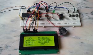
This topic shows how to make a real time clock and calendar with 2 alarms using PIC16F877A microcontroller, 2004 LCD and DS1307 serial RTC.
The following video shows what I’m going to do:
To see how to interface the DS1307 RTC chip with PIC16F877A to make a real time clock read the following topic:
Real time clock using PIC16F877A microcontroller and DS1307 serial RTC
About DS1307 RTC IC:
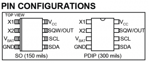
The DS1307 is an 8-pin integrated circuit uses I2C communication protocol to communicate with master device which is in our case the PIC16F877A microcontroller. This small chip can count seconds, minutes, hours, day, date, month and year with leap-year up to year 2100.
The DS1307 receives and transfers data (clock data and calendar data) as BCD format, so after receiving data we have to convert these data into decimal data, and before writing data to the DS1307 we have to convert this data from decimal to BCD format. For example we have the BCD number 33, converting this number into decimal gives 21.
The following image shows the DS1307 pin configurations:
And the following circuit is typical operating circuit for the DS1307 RTC:
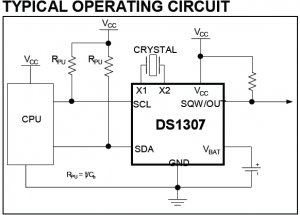
A 3V battery can be connected between VBAT and GND as a backup supply input which keeps the DS1307 oscillator running when the main power supply of the circuit is off.
The DS1307 uses an external 32.768KHz crystal and there is no need to add any resistors or capacitors with it.
More informations in the DS1307 RTC datasheet.
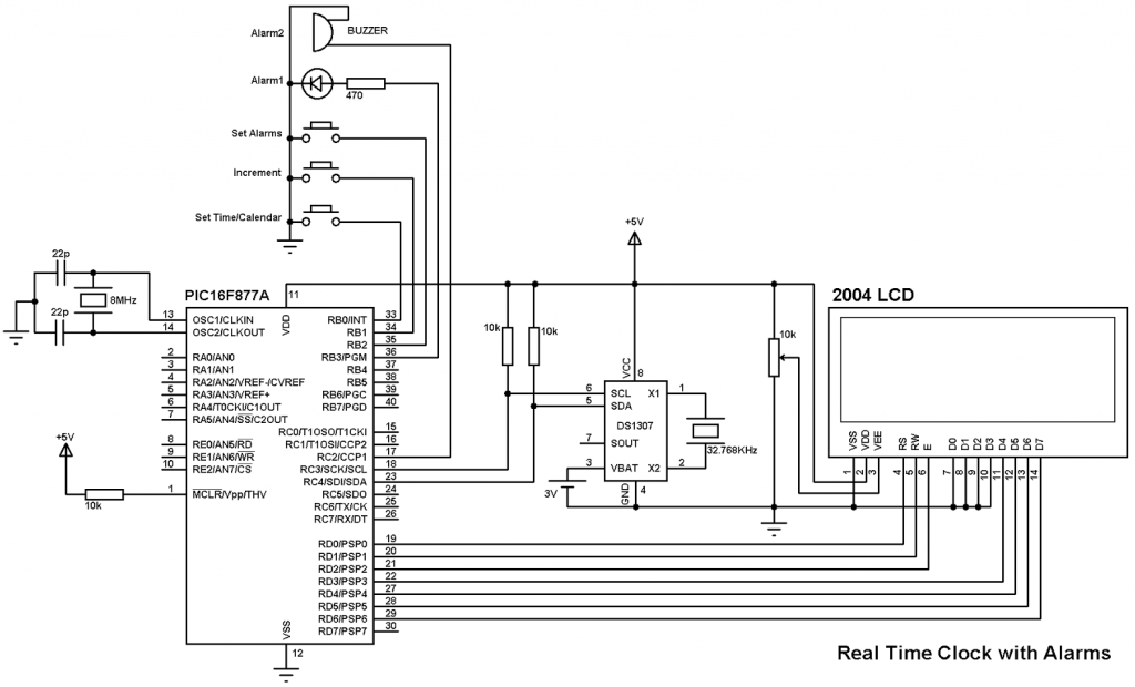
RTC with 2 alarms using PIC16F877A and DS1307 circuit:
Project circuit schematic is shown below.
Hardware Required:
- PIC16F877A Microcontroller
- DS1307
- 2004 (20×4) LCD
- 3V Cell Battery
- 8MHz and 32.768KHz crystal oscillators
- 2 x 22pF capacitors
- 3 x 10K resistors
- 10K Potentiometer
- 470Ohm resistor
- 3 Buttons
- LED (For Alarm 1)
- Buzzer (For Alarm 2)
- +5V Power Supply
- Protoboard
- Jumper Wires
Real Time Clock with 2 Alarms using DS1307 RTCC and PIC16F877A CCS C code:
This is the full code of this project…..It is easy! be patient!
1 2 3 4 5 6 7 8 9 10 11 12 13 14 15 16 17 18 19 20 21 22 23 24 25 26 27 28 29 30 31 32 33 34 35 36 37 38 39 40 41 42 43 44 45 46 47 48 49 50 51 52 53 54 55 56 57 58 59 60 61 62 63 64 65 66 67 68 69 70 71 72 73 74 75 76 77 78 79 80 81 82 83 84 85 86 87 88 89 90 91 92 93 94 95 96 97 98 99 100 101 102 103 104 105 106 107 108 109 110 111 112 113 114 115 116 117 118 119 120 121 122 123 124 125 126 127 128 129 130 131 132 133 134 135 136 137 138 139 140 141 142 143 144 145 146 147 148 149 150 151 152 153 154 155 156 157 158 159 160 161 162 163 164 165 166 167 168 169 170 171 172 173 174 175 176 177 178 179 180 181 182 183 184 185 186 187 188 189 190 191 192 193 194 195 196 197 198 199 200 201 202 203 204 205 206 207 208 209 210 211 212 213 214 215 216 217 218 219 220 221 222 223 224 225 226 227 228 229 230 231 232 233 234 235 236 237 238 239 240 241 242 243 244 245 246 247 248 249 250 251 252 253 254 255 256 257 258 259 260 261 262 263 264 265 266 267 268 269 270 271 272 273 274 275 276 277 278 279 280 281 282 283 284 285 286 287 288 289 290 291 292 293 294 295 296 297 298 299 300 301 302 303 304 305 306 307 308 309 310 311 312 313 314 315 316 317 318 319 320 321 322 323 324 325 326 327 328 329 330 331 332 333 334 335 336 337 338 339 340 341 342 343 344 345 346 347 348 349 350 351 352 353 354 355 356 357 358 359 360 361 362 363 364 365 366 367 368 369 370 371 372 373 374 375 376 377 378 | // Real time clock with alarm using PIC16F877A and DS1307 RTCC CCS C code //LCD module connections #define LCD_RS_PIN PIN_D0 #define LCD_RW_PIN PIN_D1 #define LCD_ENABLE_PIN PIN_D2 #define LCD_DATA4 PIN_D3 #define LCD_DATA5 PIN_D4 #define LCD_DATA6 PIN_D5 #define LCD_DATA7 PIN_D6 //End LCD module connections #include <16F877A.h> #fuses HS,NOWDT,NOPROTECT,NOLVP #use delay(clock = 8000000) #include <lcd.c> #use fast_io(B) #use I2C(master, I2C1, FAST = 100000) #use pwm (PWM1, FREQUENCY = 2400Hz, DUTY = 50, PWM_OFF) short alarm1_status, alarm2_status; char time[] = "TIME: : : "; char calendar[] = " / /20 "; char alarm1[] = "ALARM1: : :00 "; char alarm2[] = "ALARM2: : :00 "; unsigned int8 second, second10, minute, minute10, hour, hour10, date, date10, month, month10, year, year10, day, alarm1_minute, alarm1_hour, alarm2_minute, alarm2_hour; void ds1307_display(){ second10 = (second & 0x70) >> 4; second = second & 0x0F; minute10 = (minute & 0x70) >> 4; minute = minute & 0x0F; hour10 = (hour & 0x30) >> 4; hour = hour & 0x0F; date10 = (date & 0x30) >> 4; date = date & 0x0F; month10 = (month & 0x10) >> 4; month = month & 0x0F; year10 = (year & 0xF0) >> 4; year = year & 0x0F; time[16] = second + 48; time[15] = second10 + 48; time[13] = minute + 48; time[12] = minute10 + 48; time[10] = hour + 48; time[9] = hour10 + 48; calendar[9] = year + 48; calendar[8] = year10 + 48; calendar[4] = month + 48; calendar[3] = month10 + 48; calendar[1] = date + 48; calendar[0] = date10 + 48; lcd_gotoxy(1, 1); // Go to column 1 row 1 printf(lcd_putc, time); // Display time lcd_gotoxy(1, 2); // Go to column 1 row 2 switch(day){ case 1: lcd_putc("DATE:Sun "); break; case 2: lcd_putc("DATE:Mon "); break; case 3: lcd_putc("DATE:Tue "); break; case 4: lcd_putc("DATE:Wed "); break; case 5: lcd_putc("DATE:Thu "); break; case 6: lcd_putc("DATE:Fri "); break; case 7: lcd_putc("DATE:Sat "); break;} lcd_gotoxy(10, 2); // Go to column 10 row 2 printf(lcd_putc, calendar); // Display calendar } void alarm_display(){ // Display alarms info lcd_gotoxy(21, 1); // Go to column 1 row 3 if(alarm1_status){ alarm1[13] = alarm1_minute % 10 + 48; alarm1[12] = alarm1_minute/10 + 48; alarm1[10] = alarm1_hour%10 + 48; alarm1[9] = alarm1_hour/10 + 48; printf(lcd_putc, alarm1);} else lcd_putc("ALARM1: OFF "); lcd_gotoxy(21, 2); if(alarm2_status){ alarm2[13] = alarm2_minute % 10 + 48; alarm2[12] = alarm2_minute/10 + 48; alarm2[10] = alarm2_hour%10 + 48; alarm2[9] = alarm2_hour/10 + 48; lcd_gotoxy(21, 2); // Go to column 1 row 4 printf(lcd_putc, alarm2);} else lcd_putc("ALARM2: OFF "); } void ds1307_write(unsigned int8 address, data_){ i2c_start(); // Start I2C i2c_write(0xD0); // DS1307 address i2c_write(address); // Send register address i2c_write(data_); // Write data to the selected register i2c_stop(); // Stop I2C } void ds1307_read(){ i2c_start(); // Start I2C i2c_write(0xD0); // DS1307 address i2c_write(0); // Send register address i2c_start(); // Restart I2C i2c_write(0xD1); // Initialize data read second =i2c_read(1); // Read seconds from register 0 minute =i2c_read(1); // Read minuts from register 1 hour = i2c_read(1); // Read hour from register 2 day = i2c_read(1); // Read day from register 3 date = i2c_read(1); // Read date from register 4 month = i2c_read(1); // Read month from register 5 year = i2c_read(0); // Read year from register 6 i2c_stop(); // Stop I2C } void alarm_check(){ if((alarm1_minute == ((minute & 0x0F) + (minute >> 4) * 10)) && (alarm1_hour == ((hour & 0x0F) + (hour >> 4) * 10)) && (second == 0) && alarm1_status) output_high(PIN_B3); if((alarm2_minute == ((minute & 0x0F) + (minute >> 4) * 10)) && (alarm2_hour == ((hour & 0x0F) + (hour >> 4) * 10)) && (second == 0) && alarm2_status) pwm_on(); } void main(){ port_b_pullups(TRUE); // Enable PORTB pull-ups output_b(0); set_tris_b(7); // Configure RB0 & RB1 as inputs lcd_init(); // Initialize LCD module lcd_putc('\f'); // LCD clear while(TRUE){ if(input(PIN_B0) == 0){ // Convert BCD to decimal minute = minute + minute10 * 10; hour = hour + hour10 * 10; date = date + date10 * 10; month = month + month10 * 10; year = year + year10 * 10; // End conversion lcd_gotoxy(1, 1); // Go to column 1 row 1 lcd_putc(" Minutes: "); lcd_gotoxy(1, 2); lcd_putc(" "); delay_ms(200); while(TRUE){ if(input(PIN_B1) == 0) minute++; if(minute > 59) minute = 0; lcd_gotoxy(10, 2); // Go to column 10 row 2 printf(lcd_putc,"%02u", minute); if(input(PIN_B0) == 0) break; delay_ms(200); } lcd_gotoxy(7, 1); // Go to column 7 row 1 lcd_putc(" Hour: "); lcd_gotoxy(10, 2); // Go to column 10 row 2 lcd_putc(" "); delay_ms(200); while(TRUE){ if(input(PIN_B1) == 0) hour++; if(hour > 23) hour = 0; lcd_gotoxy(10, 2); // Go to column 10 row 2 printf(lcd_putc,"%02u", hour); if(input(PIN_B0) == 0) break; delay_ms(200); } lcd_gotoxy(9, 1); // Go to column 9 row 1 lcd_putc("Day: "); lcd_gotoxy(10, 2); // Go to column 10 row 2 lcd_putc(" "); delay_ms(200); while(TRUE){ if(input(PIN_B1) == 0) day++; if(day > 7) day = 1; lcd_gotoxy(6, 2); // Go to column 6 row 2 switch(day){ case 1: lcd_putc(" Sunday "); break; case 2: lcd_putc(" Monday "); break; case 3: lcd_putc(" Tuesday "); break; case 4: lcd_putc("Wednesday"); break; case 5: lcd_putc("Thursday "); break; case 6: lcd_putc(" Friday "); break; case 7: lcd_putc(" Saturday"); break;} if(input(PIN_B0) == 0) break; delay_ms(200); } lcd_gotoxy(9, 1); // Go to column 9 row 1 lcd_putc("Date:"); lcd_gotoxy(6, 2); // Go to column 6 row 2 lcd_putc(" "); delay_ms(200); while(TRUE){ if(input(PIN_B1) == 0) date++; if(date > 31) date = 1; lcd_gotoxy(10, 2); // Go to column 10 row 2 printf(lcd_putc,"%02u", date); if(input(PIN_B0) == 0) break; delay_ms(200); } lcd_gotoxy(8, 1); // Go to column 8 row 1 lcd_putc("Month"); lcd_gotoxy(10, 2); // Go to column 10 row 2 lcd_putc(" "); delay_ms(200); while(TRUE){ if(input(PIN_B1) == 0) month++; if(month > 12) month = 1; lcd_gotoxy(10, 2); // Go to column 10 row 2 printf(lcd_putc,"%02u", month); if(input(PIN_B0) == 0) break; delay_ms(200); } lcd_gotoxy(8, 1); lcd_putc(" Year"); lcd_gotoxy(9, 2); lcd_putc("20 "); delay_ms(200); while(TRUE){ if(input(PIN_B1) == 0) year++; if(year > 99) year = 0; lcd_gotoxy(11, 2); printf(lcd_putc,"%02u", year); if(input(PIN_B0) == 0){ // Convert decimal to BCD minute = ((minute/10) << 4) + (minute % 10); hour = ((hour/10) << 4) + (hour % 10); date = ((date/10) << 4) + (date % 10); month = ((month/10) << 4) + (month % 10); year = ((year/10) << 4) + (year % 10); // End conversion ds1307_write(1, minute); ds1307_write(2, hour); ds1307_write(3, day); ds1307_write(4, date); ds1307_write(5, month); ds1307_write(6, year); ds1307_write(0, 0); delay_ms(200); break; } delay_ms(200); } } if(input(PIN_B2) == 0){ lcd_gotoxy(21, 1); lcd_putc(" ALARM1: "); lcd_gotoxy(21, 2); lcd_putc(" "); delay_ms(200); while(TRUE){ ds1307_read(); ds1307_display(); if(input(PIN_B1) == 0) alarm1_status++; if(alarm1_status){ lcd_gotoxy(30, 2); lcd_putc("ON ");} else{ lcd_gotoxy(30, 2); lcd_putc("OFF");} if(input(PIN_B2) == 0) break; delay_ms(200);} if(alarm1_status){ lcd_gotoxy(21, 1); lcd_putc(" ALARM1 Minutes:"); lcd_gotoxy(21, 2); lcd_putc(" "); delay_ms(200); while(TRUE){ ds1307_read(); ds1307_display(); if(input(PIN_B1) == 0) alarm1_minute++; if(alarm1_minute > 59) alarm1_minute = 0; lcd_gotoxy(30, 2); printf(lcd_putc,"%02u", alarm1_minute); if(input(PIN_B2) == 0) break; delay_ms(200); } lcd_gotoxy(21, 1); lcd_putc(" ALARM1 Hour: "); lcd_gotoxy(21, 2); lcd_putc(" "); delay_ms(200); while(TRUE){ ds1307_read(); ds1307_display(); if(input(PIN_B1) == 0) alarm1_hour++; if(alarm1_hour > 23) alarm1_hour = 0; lcd_gotoxy(30, 2); printf(lcd_putc,"%02u", alarm1_hour); if(input(PIN_B2) == 0) break; delay_ms(200); }} lcd_gotoxy(21, 1); lcd_putc(" ALARM2: "); lcd_gotoxy(21, 2); lcd_putc(" "); delay_ms(200); while(TRUE){ ds1307_read(); ds1307_display(); if(input(PIN_B1) == 0) alarm2_status++; if(alarm2_status){ lcd_gotoxy(30, 2); lcd_putc("ON ");} else{ lcd_gotoxy(30, 2); lcd_putc("OFF");} if(input(PIN_B2) == 0) break; delay_ms(200);} if(alarm2_status){ lcd_gotoxy(21, 1); lcd_putc(" ALARM2 Minutes:"); lcd_gotoxy(21, 2); lcd_putc(" "); delay_ms(200); while(TRUE){ ds1307_read(); ds1307_display(); if(input(PIN_B1) == 0) alarm2_minute++; if(alarm2_minute > 59) alarm2_minute = 0; lcd_gotoxy(30, 2); printf(lcd_putc,"%02u", alarm2_minute); if(input(PIN_B2) == 0) break; delay_ms(200); } lcd_gotoxy(21, 1); lcd_putc(" ALARM2 Hour: "); lcd_gotoxy(21, 2); lcd_putc(" "); delay_ms(200); while(TRUE){ ds1307_read(); ds1307_display(); if(input(PIN_B1) == 0) alarm2_hour++; if(alarm2_hour > 23) alarm2_hour = 0; lcd_gotoxy(30, 2); printf(lcd_putc,"%02u", alarm2_hour); if(input(PIN_B2) == 0) break; delay_ms(200); }} delay_ms(200); } if(input(PIN_B1) == 0){ output_low(PIN_B3); pwm_off(); } ds1307_read(); // Read data from DS1307 RTCC alarm_check(); // Check if there is an alarm ds1307_display(); // Diaplay time and calendar alarm_display(); // Display alarms delay_ms(50); } } |

what is the error in this line (line 19)
#use pwm (PWM1, FREQUENCY = 2400Hz, DUTY = 50, PWM_OFF)
An error occurred in line 19 while compiling. Error 44: Internal Error – Contact CCS PPUSE. How do I correct it?
comment corrige le problème
if the MCU will work 100 % full time, why you use DS1307, use just the timer and burn the MCU
An error occurred in line 19 while compiling. Line 17(6,56)Error 44:Internal Error – Contact CCS PPUSE. How do I correct it?
give me Hex file
An error occurred in line 19 while compiling. Line 17(6,56)Error 44:Internal Error – Contact CCS PPUSE. How do I correct it?
How did you correct me gave the same error
An error occurred in line 19 while compiling. Error 44: Internal Error – Contact CCS PPUSE. How do I correct it?