This topic shows how to control speed and direction of rotation of two DC motors using 2-axis joystick (PS2 joystick) and PIC16F877A microcontroller.
The PS2 Joystick consists of two potentiometers (one for the X-axis and the other for the Y-axis) and a push-button. With one potentiometer we can control the speed and rotation direction of a DC motor.
Hardware Required:
- PIC16F877A microcontroller —> datasheet
- PS2 Joystick
- L293D motor driver IC — datasheet
- 2 x 12V DC motor
- 8 MHz crystal oscillator
- 2 x 22pF ceramic capacitors
- 10k ohm resistor
- 12V source
- 5V source
- Breadboard
- Jumper wires
The L293D motor dirver IC is quadruple half-H drivers chip which allows to drive two motors in both directions, and with the two PWM modules on the PIC16F877A microcontroller we can easily control the rotation speed of the two motors. (PWM: Pulse Width Modulation).
As mentioned above the PIC16F877A microcontroller has two CCP (Capture/Compare/PWM) modules which can generate two independent PWM signals (but with the same frequency). The speed of a DC motor can be controlled with the variation of the duty cycle of the PWM signal. The output pins of PWM1 and PWM2 are RC2 and RC1 respectively.
Joystick controlled DC motor with PIC16F877A circuit:
The following image shows the circuit schematic diagram of this example.
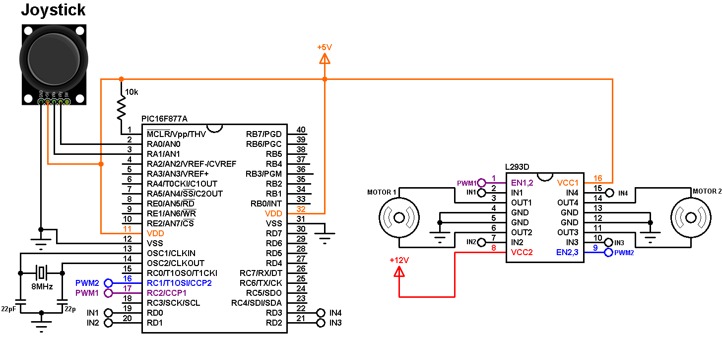
(All grounded terminals are connected together)
The L293D driver has 2 VCCs: VCC1 is +5V and VCC2 is +12V (same as motor nominal voltage). Pins IN1/IN3 and IN2/IN4 are the control pins where (IN1 and IN2 for motor 1; IN3 and IN4 for motor 2):
| IN1/IN3 | IN2/IN4 | Function |
| L | H | Direction 1 |
| H | L | Direction 2 |
| L | L | Fast motor stop |
| H | H | Fast motor stop |
The joystick board has 5 terminals: GND, +5V, VRX, VRY and SW where:
GND and +5V are power supply pins
VRX is the X-axis potentiometer output
VRY is the Y-axis potentiometer output
SW is the push button terminal (the other terminal is connected to GND).
The outputs of the X-axis and Y-axis potentiometers are connected to analog pins AN0 and AN1 respectively. The switch pin (SW) is not used in this example.
PWM1 pin (RC2) is connected to EN1,2 pin (#1) and PWM2 pin (RC1) is connected to EN2,3 pin (#9) of the L293D. The other L293D pins which are IN1, IN2, IN3 and IN4 are connected to RD0, RD1, RD2 and RD3 respectively.
Motor 1 rotation speed is controlled by PWM1 and its direction of rotation is controlled by pins IN1 and IN2. If IN1 and IN2 are zeroes the motor stops, if IN1 = 1 and IN2 = 0 the motor rotates in the one direction, if IN1 = 0 and IN2 = 1 the motor rotates in the other direction.
The same thing for motor 2 with pins PWM2, IN3 and IN4.
In the circuit there are two power supply sources, 5V and 12V. The 5V supplies most of the circuit including the microcontroller whereas the 12V supplies one pin of the L293D (VCC2). The 12V power supply source depends on the motor nominal voltage, for example if the motor nominal voltage is 5V, VCC2 pin should be connected to +5V source.
Joystick controlled DC motor with PIC16F877A CCS C code:
Timer2 module is configured to generate PWM signals of 3.9 KHz with a resolution of 9 bits :
setup_timer_2(T2_DIV_BY_4, 127, 1);
Where: T2_DIV_BY_4 is Timer2 prescaler (prescaler = 4)
127 is Timer2 preload value
1 is Timer2 postoscaler (not used in calculations)
The PWM frequency can be calculated using the following equation:
Where the PWM frequency = 1/ PWM period
PR2: Timer2 preload value
TOSC = 1/MCU frequency (in this example MCU frequency = 8MHz)
The resolution of the PWM signal can be calculated using the following equation:
Resolution = ———————— bits
log(2)
With a 9-bit resolution the duty cycle of each PWM signal can vary in the interval [0, 511].
CCS C code:
1 2 3 4 5 6 7 8 9 10 11 12 13 14 15 16 17 18 19 20 21 22 23 24 25 26 27 28 29 30 31 32 33 34 35 36 37 38 39 40 41 42 43 44 45 46 47 48 49 50 51 52 53 54 55 56 57 58 59 60 61 62 63 64 | // Two DC motors control with PIC16F877A and joystick CCS C code. #include <16F877A.h> #device ADC = 10 #fuses HS,NOWDT,NOPROTECT,NOLVP #use delay(clock = 8MHz) signed int16 motor1_pot, motor2_pot; void main() { setup_adc(ADC_CLOCK_INTERNAL); // ADC module uses its internal oscillator setup_adc_ports(AN0_AN1_AN3); // Configure AN0, AN1 and AN3 as analog pins setup_timer_2(T2_DIV_BY_4, 127, 1); // Set PWM frequency to 3.9 KHz with 9-bit resolution setup_ccp1(CCP_PWM); // Configure CCP1 module as PWM setup_ccp2(CCP_PWM); // Configure CCP2 module as PWM set_pwm1_duty(0); // Set PWM1 duty cycle set_pwm2_duty(0); // Set PWM2 duty cycle delay_ms(1000); // Wait 1 second while(TRUE) { set_adc_channel(0); // Select channel AN0 delay_ms(10); // Wait 10 ms motor1_pot = read_adc(); // Read from AN0 and store in motor1_pot set_pwm1_duty(abs(motor1_pot - 511)); // Set motor 1 PWM duty cycle (abs => absolute value) set_adc_channel(1); // Select channel AN0 delay_ms(10); // Wait 10 ms motor2_pot = read_adc(); // Read from AN0 and store in motor2_pot set_pwm2_duty(abs(motor2_pot - 511)); // Set motor 2 PWM duty cycle (abs => absolute value) // Motor 1 control if(motor1_pot > 520) { // Motor 1 first direction output_low(PIN_D1); output_high(PIN_D0); } else { if(motor1_pot < 500) { // Motor 1 second direction output_low(PIN_D0); output_high(PIN_D1); } else { // Motor 1 stop output_low(PIN_D0); output_low(PIN_D1); } } // Motor 2 control if(motor2_pot > 520) { // Motor 2 first direction output_low(PIN_D3); output_high(PIN_D2); } else { if(motor2_pot < 500){ // Motor 2 second direction output_low(PIN_D2); output_high(PIN_D3); } else { // Motor 2 stop output_low(PIN_D2); output_low(PIN_D3); } } } } |
The video below shows a simple hardware circuit of this example:

Bro can u send embedded c code for this project